Series and parallel connections

All circuits are built out of two types of electrical connections that determine the characteristics of the circuit: series and parallel. Any devices that has more than one battery, like a radios or a flashlight, uses either a series or parallel connection to achieve a desired voltage or desired amount of available energy. All batteries have a positive and a negative electrode which are the points where electrical connections are made. When the positive electrode of a batteries is connected to the negative of another battery, this is called a series connection. This series connection will increase the circuit voltage. When the positive electrode of a battery is connected to the positive electrode of another battery and the negative electrode is connected to the negative electrode of the same battery, this is called a parallel connection. This parallel connection will keep the circuit voltage the same, but will increase the current available to the circuit.
In PV systems, series connections become important as they enable the voltage and current characteristics of a system to be varied which offers important advantages. Batteries and PV modules can be connected using either of these connection types or both. All batteries, PV modules, charge controllers and inverters are rated to operate within a given voltage and current range, thus these connection types are used to sure that the system can function together properly.
It is important to note that for circuits inside of homes and buildings for appliances or lighting only ever use parallel connections.
Contents
Parallel connections
A parallel connection is a connection that brings together circuits the could operate separately, thus there are two or more separate paths current can follow. In the case of PV modules and batteries this is done by creating a connection between all of the positive connections of the circuits and a separate connection between all of the negative connections of a circuit. Parallel connections affect the functioning of a circuit in the following ways:
- If power sources, like PV modules or batteries, of the same size are connected together in parallel, the voltage of the circuit remains the same, but the current that the circuit can provide becomes the sum of their currents.
- If loads, like a lights, of the same size are connected together in parallel, the voltage of the circuit will remain the same, but the current of the circuit will be divided between the different parallel circuits.
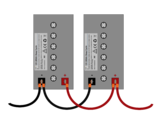
2 x 12V FLA batteries connected with a parallel connection.
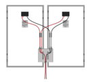
2 x PV modules connected with a parallel connection in a combiner box.


Example 1: 2 x 12V 100Ah (at a C/20 discharge rate) batteries are connected in parallel. What is the voltage of the circuit and the Ah of available current at the C/20 rate?
- V = 12 V as the voltage stays the same.
- Ah = 200 Ah as the Ah of available current doubles in this case.
Example 2: 3 x PV modules with an open circuit voltage (Voc) of 40 V and a short-circuit current (Isc) of 10 A are connected in parallel. What is the voltage and available current of the circuit?
- V = 40 V as the voltage stays the same.
- Ah = 30 A as the current triples in this case.
Example 3: 2 x 12 W lightbulbs (12 V, 1 A) are connected in parallel to a battery. What is the voltage and current across each lightbulb and for the circuit in total?
- Each lightbulb
- V = 12 V
- I = 1 A
- Circuit total
- V = 12 V
- I = 1 A + 1 A = 2 A
Series connections
A series connection is a connection that brings together loads or power sources into one single circuit, thus there is only one path that the current can follow. In the case of PV modules and batteries this is done by creating a connection from the positive of one load/power source to the negative of another. Series circuits affect the functioning of a circuit in the following ways:
- If power sources, like PV modules or batteries, of the same size are connected together in series, the voltage of the circuit becomes the sum of their voltages, but the available current of the circuit remains the same.
- If two loads, like a lights, of the same size are connected together in series, the voltage of the circuit is divided between the different loads, but the current of the circuit remains the same.
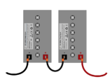
2 x 12V FLA batteries connected with a series connection.
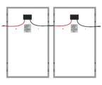
2 x PV modules connected with a series connection.


Example 1: 2 x 12V 100Ah (at a C/20 discharge rate) batteries are connected in series. What is the voltage of the circuit and the Ah of available current at the C/20 discharge rate?
- V = 24 V as the voltage doubles in this case.
- Ah = 100 Ah as the available current remains the same.
Example 2: 3 x PV modules with an open circuit voltage (Voc) of 40V and a short circuit current (Isc) of 10A are connected in series. What is the voltage and available current of the circuit?
- V = 120 V as the voltage triples in this case.
- Ah = 10 A as the current tripes in this case.
Example 3: 2 x 12 W lightbulbs (12 V, 1 A) are connected in series to a 12V battery. What is the voltage and current across each lightbulb and for the circuit in total?
- Each lightbulb
- V = 12 V ÷ 2 = 6 V
- I = 1 A
- Circuit total
- V = 12 V
- I = 1 A (same 1A passes through each lightbulb)
Series vs. parallel
Series and parallel connections only change the characteristics of the circuit, but there is no power or energy that is gained or lost with either connection type. Then when should you use a series connection or a parallel connection? Choosing the correct connection type for a particular circuit depends upon various factors.
Power with different connection types
Example 1: 3 x PV modules with an open circuit voltage (Voc) of 40 V and a short circuit current (Isc) of 10 A are connected in parallel. What is the voltage and available current of the circuit?
- (3 × 10 A) × 40V = 1200W
Example 2: 3 x PV modules with an open circuit voltage (Voc) of 40 V and a short circuit current (Isc) of 10 A are connected in series. What is the voltage and available current of the circuit?
- 10 A × (3 x 40 V) = 1200 W
When to use series and parallel
The type of connection is ideal for a circuit depends upon the components that will be used with the circuit. All components used in an electrical system have specific maximum current and maximum voltage ratings, but PV specific components like charge controllers and inverters also have minimum voltage requirements to function properly. The other important factor in determining the connection type is that increases in current require larger conductors to avoid electrical fires, yet voltage does not suffer from the same challenges. Increasing the voltage of a circuit can be used to increase the amount of power that a circuit is capable of carrying without the necessity of increasing the size of the conductor. This means that a higher voltage, as long as it is within the maximum voltage limits of all of the components in the system, is typically preferrable as it reduces the size of conductors needed for a PV system. Using a higher voltage is an important strategy to keep voltage drop and system cost to a minimum.
It is typical for an off-grid PV system to use a combination of parallel and series connections to be able to be able to match the design requirements of the system with the available equipment. Equipment for use with off-grid PV systems is only available in a few specific nominal voltage ratings (12V, 24V, 48V), specific maximum voltage ratings, and specific maximum current ratings. A combination of these different connection types allow system designs to choose the voltage and combination of components that will offer the best performance at the lowest price. See Special:MyLanguage/DC system voltage for more information about choosing the ideal voltage for a particular system.