Simplified wire, overcurrent protection, and disconnect sizing and selection

Choosing the proper wire (conductor) size for a circuit is necessary to ensure that a system is safe and functions properly. In order to determine the appropriate wire size for a particular circuit there are four main considerations that must be evaluated:
- Maximum circuit current: determined by the powersource(s) or load(s) that are a part of the circuit.
- Wire ampacity: minimum size is determined by the maximum circuit current of the circuit and the conditions of use.
- Overcurrent protection and disconnects: minimum size is determined by the maximum circuit current.
- Voltage drop: minimum wire size is determined by the operating voltage, operating current, wire size, and one-way length of the circuit.
There are some circuits that may not exist in all PV systems, for example:
- If there is no inverter then there will be no inverter input, inverter output, or AC branch circuits.
- If the system has no DC lighting or loads, there will be no DC load circuits or DC branch circuits.
- If there is no combiner box then there will be no PV output circuit.
- If the inverter and charge controller are connected directly to the energy storage system, then there will be no energy storage circuit.
The charts below can be used to deteremine appropriate wire and overcurrent protection device sizes for all of the wires in a typical standalone PV system, but only if they meet the following criteria:
- Should have a 75°C or 90°C temperature rating
- There are less than 3 current-carrying conductors in a conduit.
- The ambient temperature where the PV source and PV output wires will be run should not exceed 45°C during the year.
- For circuits other than the PV source and PV output circuit, the ambient temperature where the wires will be run should not exceed 30°C.
If the wires in the system do not meet this criteria, then wire and overcurrent protection device sizing should be done using the more detailed wire, overcurrent protection, and disconnect sizing and selection process.
Contents
- 1 Overcurrent protection and disconnects
- 2 Recommended circuit voltage drop values
- 3 Wire, OCPD, and disconnect sizing
Overcurrent protection and disconnects


No wire should be exposed to current in excess of its rated capacity under the conditions of use. If a power source that a circuit is connected to can supply more current than the rated ampacity of a wire, then an overcurrent protection device must be used to prevent it from overheating and starting a fire. In off-grid systems overcurrent protection devices are also typically used as power source disconnects and equipment disconnects. OCPD - fuses and breakers - come in standard sizes that should be used in any design:
- Standard international OCPD sizes: 1 A, 2 A, 4 A, 6 A, 10 A, 13 A, 16 A, 20 A, 25 A, 32 A, 40 A, 50 A, 63 A, 80 A, 100 A, 125 A, 150 A, 175 A, 200 A, and 225 A.
- Standard US OCPD sizes per US NEC: 15, 20, 25, 30, 35, 40, 45, 50, 60, 70, 80, 90, 100, 110, 125, 150, 175, 200, 225, 250, 300, 350, 400, 450, 500, 600, 700, 800, 1000, 1200, 1600, 2000, 2500, 3000, 4000 5000, and 6000 A. Additional standard fuse sizes are 1, 3, 6, 10, and 601 A.
Residual current devices should be sized using this same method if they are intended to function as an OCPD, if not they only need to be larger than the maximum current of the circuit to ensure that they do not accidentally trip.
Ground fault protection devices incorporate a breaker, but these GFPDs only come in a few sizes and it is common to use a GFPD with a breaker that is substantially larger than the ampacity of the wire for this reason. An additional breaker is therefore commonly used as the power source disconnect, because using the GFPD would mean that the DC system bond would be removed each time the breaker was used as a disconnect, which is not a safe practice.
There are some cases in which an overcurrent protection device is not required because another overcurrent protection device protects that circuit against excessive current or the power source cannot supply current that would exceed the rated capacity of the wire. Not all systems are wired the same - some designs will require additional OCPDs and others will require fewer.
| Circuit | |
|---|---|
| (1) PV source circuit OCPD | Required if the system has more than two parallel strings of PV modules. Can also serve as the required power source disconnect - see (10) in the image. |
| (2) PV output circuit OCPD | A power source disconnect - typically a breaker - is required for the PV source. If the PV source circuits have breakers they can meet this need if they are located near the charge controller. Can also serve as the required power source disconnect - see (10) in the image. |
| (3) Charge controller output circuit OCPD | The wires between the charge controller and the energy storage system must be protected by an OCPD. There should also be a power source disconnect for the energy storage system and an equipment disconnect for the charge controller. Both of these requirements can be fulfilled by installing a breaker - see (11) in the image. |
| (4) Charge controller load circuit OCPD | The wires between the charge controller and any lighting/load only need to be protected by an OCPD if the charge controller can supply current that exceeds the rating of the wires. This is typically not the case. |
| (5) DC branch circuit OCPD | The wires between the charge controller and any lighting/loads only need to be protected by an OCPD if the charge controller can supply current that exceeds the rating of the wires. This is typically not the case. |
| (6) Inverter input circuit OCPD | The wires between the inverter and the energy storage system must be protected by an OCPD. There should also be a power source disconnect for the energy storage system and an equipment disconnect for the inverter. Both of these requirements can be fulfilled by installing a breaker - see (13) in the image. |
| (7) Inverter output circuit OCPD | The wires between the inverter and any loads only need to be protected by an OCPD if the inverter can supply current that exceeds the rating of the wires. This is often not the case with smaller inverters, especially those with a 220 V nominal voltage. It is recommended that a residual current device (RCD) with an integrated breaker is used on the output of the inverter to increase system safety or on each individual circuit. It should be located before the AC system bonding jumper to avoid accidental tripping (activation). |
| (8) AC branch circuit OCPD | The wires between the inverter and any loads only need to be protected by an OCPD if the inverter can supply current that exceeds the rating of the wires. This is often not the case with smaller inverters, especially those with a 220 V nominal voltage. If there is no residual current device (RCD) on the output circuit of the inverter, it is recommended that one be added to AC circuit or outlet. |
| (9) Energy storage circuit OCPD | The wires between the energy storage system and any other component must be protected by an OCPD - charge controllers, inverters, DC-DC converters, low voltage disconnects, DC appliances. There also must be a power source disconnect for the energy storage system. Both of these requirements can be fulfilled by installing a breaker or a fused disconnect - see (12) in the image. Larger systems are typically designed like in the wiring diagram with one single circuit running from the energy storage system to common DC busbars to reduce wire and OCPD costs - in this case there is an energy storage circuit. Smaller systems often connect the charge controller and inverter directly to the energy storage system independently - in this case there is no energy storage circuit. |
Recommended circuit voltage drop values
The table below has recommended maximum voltage drop values for various circuits. It is important to note that other components in a circuit - terminals, fuses, breakers - add resistance and will increase voltage drop as well, therefore it is important to be conservative.
Note: Not all PV systems are wired the same. These voltage drop values are for total circuit length between one component and another. It is common to have DC busbars that have one single set of wires that runs to the energy storage system and connect to a positive and negative DC busbar that serve as a point of connection for the inverter and charge controller. In this case it is necesary to calculate the total voltage drop between the charge controller and the energy storage system, rather than just to the busbar.
| Circuit | Maximum recommended voltage drop |
|---|---|
| PV source to charge controller | 3% |
| Charge controller to energy storage | 1.5% |
| Energy storage to inverter | 1.5% |
| DC lighting circuits | 5% |
| DC load circuits | 3% |
| AC load and lighting circuits | 2% |
Wire, OCPD, and disconnect sizing
Each circuit in a stand-alone PV system can be sized using the charts below. Read the instructions carefully as the charts vary.
PV source and PV output circuits
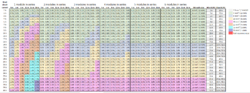
The proper size for any wires and overcurrent protection devices that run between the PV source and the charge controller should be determined together and can be determined using the short-circuit (Isc) rating of the module, number of module cells (36, 60, 70), and one-way circuit distance. The total voltage drop between the PV source and the charge controller should ideally be kept to less than 3% to avoid lost production and charging issues.
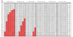
PV source circuit chart
4 mm² wire is assumed, as this is common practice.
- Estimate the one-way distance from the PV source circuit to the charge controller, combiner box, or junction box.
- Determine the number of modules in series per circuit. This is used to determine which columns to use at the top of the charge.
- Find the short-circuit current (Isc) rating of the PV module that will be used. This is used on the left side of the chart.
- Find the estimated one-way distance on the chart.
This process will give an estimated voltage drop value for the circuit and minimum/maximum OCPD size. If the recommended wire size - when combined with the PV source circuit - leads to excessive voltage drop, then the next largest wire size from the chart can be chosen. Choosing a larger wire size due to voltage drop will not require a larger OCPD.
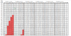
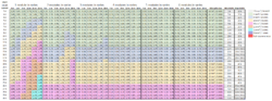
PV output circuit chart
- Estimate the distance from the combiner box or junction box to the charge controller.
- Determine the number of modules in series per circuit. This is used to determine which columns to use at the top of the charge.
- Find the estimated one-way distance on the chart.
- Add up the total short-circuit current (Isc) rating for all parallel circuits. If there are 2 parallel circuits, then the value will be Isc ×2. Find this value on the left side of the chart.
This process will give a recommended wire size - with an estimated amount of voltage drop - and a minimum/maximum OCPD size. If the recommended wire size - when combined with the PV source circuit - leads to excessive voltage drop, then the next largest wire size from the chart can be chosen. Choosing a larger wire size due to voltage drop will not require a larger OCPD.
Using the charts together
- If there is only 1 circuit and it is able to reach the charge controller with less than 3% voltage drop using a 4mm² (PV source chart), then it is not necessary to add a PV output circuit.
- If there is only 1 circuit and it is unable to reach the charge controller with less than 3% voltage drop using a 4mm² (PV source chart), then it is necessary to add a junction box to transition to a larger wire size. The junction box should be located close to the PV source to allow a voltage drop of less than 1% - use the PV source chart to determine this distance. A larger wire should then be chosen using the PV output circuit charge that has a voltage drop of less than 2%. This will give a combined voltage drop of less than 3%.
- If there is more than 1 circuit, then a combiner box should be added where circuits can be combined and the wire can be transitioned to a larger size before reaching the charge controller. The combiner box should be located close to the PV source to allow a voltage drop of less than 1% - use the PV source chart to determine this distance. A larger wire should then be chosen using the PV output circuit charge that has a voltage drop of less than 2%. This will give a combined voltage drop of less than 3%.
PV source charts
36-cell module PV source circuit sizing chart
60-cell module PV source circuit sizing chart
72-cell module PV source circuit sizing chart


PV output charts
36-cell module PV output circuit sizing chart
60-cell module PV output circuit sizing chart
72-cell module PV output circuit sizing chart


Charge controller output circuit
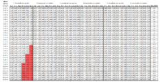
The appropriate wire size for the output circuit for both types of charge controller - PWM and MPPT - can be determined using its current rating, DC system voltage, and one-way length of the circuit. A charge controller may be connected directly to a the energy storage system, which may require several meters of wire, or it may be connected to DC busbars that are fed by the energy storage circuit. Ideally, the total voltage drop between the charge controller and the energy storage system - including the energy storage circuit - should be kept below 1.5%.
- Estimate one-way circuit length from the charge controller to either the DC busbars or the energy storage system.
- Find the correct system voltage (12 V, 24 V, 48 V) on the chart.
- Find the estimated one-way distance on the chart.
- Find the current rating of the charge controller on the left side of the chart.
This process will give a recommended wire size - with an estimated amount of voltage drop - and a minimum/maximum OCPD size. If the recommended wire size - when combined with the energy storage circuit - leads to excessive voltage drop, then the next largest wire size from the chart can be chosen. Choosing a larger wire size due to voltage drop will not require a larger OCPD.

Inverter input circuit
The appropriate wire size of the input circuit for any type of inverter can be determined using the continuous duty rating (in watts (W) or volt-amperes (VA)), DC system voltage, and one-way circuit distance. An inverter may be connected directly to a the energy storage system, which may require several meters of wire, or it may be connected to DC busbars that are fed by the energy storage circuit. Ideally, the total voltage drop between the charge controller and the energy storage system - including the energy storage circuit - should be kept below 1.5%.
- Estimate one-way circuit length from the inverter to either the DC busbars or the energy storage system.
- Find the correct system voltage (12 V, 24 V, 48 V) on the chart.
- Find the estimated one-way distance on the chart.
- Find the current continuous duty rating on the left side of the chart.
This process will give a recommended wire size - with an estimated amount of voltage drop - and a minimum/maximum OCPD size. If the recommended wire size - when combined with the energy storage circuit - leads to excessive voltage drop, then the next largest wire size from the chart can be chosen. Choosing a larger wire size due to voltage drop will not require a larger overcurrent protection device.

DC load/branch circuits
The appropriate wire size for any DC load or branch circuit can be determined using the power rating of all of the loads that could potentially be connected to the circuit, DC system voltage, and one-way length of the circuit. The DC load/branch circuit may be output from the charge controller, connected to a DC-DC converter, or may be directly connected to the DC busbar if it is a larger appliance. Ideally, the total voltage drop, including all circuits between the DC power source (charge controller, DC-DC converter, DC busbars) and the load, should be kept below 3%.
- Estimate one-way circuit length.
- Estimate the total watts of loads that will be connected to the circuit.
- Find the correct system voltage (12 V, 24 V, 48 V) on the chart.
- Find the estimated one-way distance on the chart.
- Find total circuit watts on the left side of the chart.
This process will give a recommended wire size - with an estimated amount of voltage drop - and a minimum/maximum OCPD size. If the recommended wire size - when combined with the energy storage circuit - leads to excessive voltage drop, then the next largest wire size from the chart can be chosen. Choosing a larger wire size due to voltage drop will not require a larger OCPD.

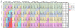
AC load/branch circuits
The appropriate wire size for the inverter output circuit or any AC branch circuit can be determined using the power rating of all of the loads that could potentially be connected to the circuit, inverter output voltage, and one-way length of the circuit. This chart will work for the inverter output circuit, which feeds all of the AC loads from a distribution panel, or for a single AC branch circuit that only feeds a few small loads. Ideally, the total voltage drop, including all circuits between the inverter and the load, should be kept below 2%.
- Estimate one-way circuit length.
- Estimate the total watts of loads that will be connected to the circuit.
- Find the correct inverter output voltage (120 V, 230 V)on the chart.
- Find the estimated one-way distance on the chart.
- Find total circuit watts on the left side of the chart.
This process will give a recommended wire size - with an estimated amount of voltage drop - and a minimum/maximum OCPD size. If the recommended wire size - when combined with the energy storage circuit - leads to excessive voltage drop, then the next largest wire size from the chart can be chosen. Choosing a larger wire size due to voltage drop will not require a larger OCPD.

Energy storage circuit
The wire and OCPD for the energy storage cirucit is sized using the size of the overcurrent protection devices (OCPDs) and wires, determined using the charts, for the charge controller output circuit and inverter input circuit (if the system has an inverter). Ideally, the total voltage drop, including all circuits between the energy storage system and any other system components should be kept below 1.5%. The following process can be used:
- Determine the one-way distance from the DC busbars to the energy storage system.
- Determine which OCPD value is higher: the charge controller output circuit OCPD or the inverter input circuit OCPD. This OCPD size can also be used as the OCPD and power source disconnected for the energy storage system.
- On the chart of the component with the higher OCPD value, find the intersection between the current rating (charge controller) or power rating (inverter) and the one-way distance of the energy storage circuit.
This process will give a recommended wire size - with an estimated amount of voltage drop - and a minimum/maximum OCPD size. If the recommended wire size - when combined with the previously calculated voltage drop for charge controller output circuit or inverter input circuit - leads to excessive voltage drop, then the next largest wire size from the chart can be chosen. Choosing a larger wire size due to voltage drop will not require a larger overcurrent protection device.