Detailed DC system design
Location: Pampachiri, Apurimac, Peru
GPS coordinates: -14.1870656, -73.5445298
Altitude: 3378 m
Description: A two story adobe home in the Peruvian Andes with only DC power needs. The home is used all year and the loads are used consistently throughout the year. Load usage is primarily during the evening/night. The homeowners do not intend on adding any major appliances in the near future.

Photo of the home.

Location of the home.


Contents
- 1 Load evaluation
- 2 Weather and solar resource evaluation
- 3 Load and solar resource comparison
- 4 Design parameters
- 5 Energy storage sizing and selection
- 6 Minimum PV source size
- 7 PWM charge controller sizing and selection
- 7.1 Step 1: Determine PV module power rating
- 7.2 Step 2: Determine proposed module configuration
- 7.3 Step 3: Verify excess production
- 7.4 Step 4: Verify charging current
- 7.5 Step 5: Determine final number of PV modules
- 7.6 Step 6: Total PV source current
- 7.7 Step 7: Select a charge controller
- 7.8 Step 8: Determine final PV source power rating
- 7.9 Step 9: Verify PV source and charge controller compatability
- 8 Wire, overcurrent protection, and disconnect sizing and selection
- 9 Design summary
- 10 Notes/references
Load evaluation
Step 1: Fill out DC load chart
| April - September | October - March | ||||||||||
|---|---|---|---|---|---|---|---|---|---|---|---|
| # | Load | Quantity | Watts | Total watts | Duty cycle | Hours per day | Days per week | Average daily DC watt-hours | Hours per day | Days per week | Average daily DC watt-hours |
| 1 | LED light | 6 | 5 W | 30 W | 1 | 3 hours | 7 days | 90 Wh | 3 hours | 7 days | 90 Wh |
| 2 | Radio | 1 | 6 W | 6 W | 1 | 5 hours | 7 days | 30 Wh | 5 hours | 7 days | 30 Wh |
| 3 | Cell phone | 2 | 10 W | 20 W | 1 | 1 hours | 7 days | 20 Wh | 1 hours | 7 days | 20 Wh |
- Load: The make and model or type of load.
- Quantity: The number of the particular load.
- Watts: The power rating in watts of the load.
- Total watts = Quantity × Watts
- Duty cycle = Rated or estimated duty cycle for the load. If the load has no duty cycle a value of 1 should be used. A load with a duty cycle of 20% would be inputted as .2
- Hours per day: The maximum number of hours the load(s) will be operated per day. If the load has a duty cycle 24 hours should be used.
- Days per week: The maximum number of days the load(s) will be operated per week.
- Average daily DC watt-hours = Total watts × Duty cycle × Hours per day × Days per week ÷ 7 days
Step 2: Determine DC energy demand
| Total average daily DC watt-hours (April - September) | = sum of Average daily DC watt-hours for all loads for April - September |
|---|---|
| = 140 Wh |
| Total average daily DC watt-hours (October - March) | = sum of Average daily DC watt-hours for all loads for October - March |
|---|---|
| = 140 Wh |
Total average daily energy demand
The total energy demand for the system is the added Average daily DC-watt hours and Average daily AC watt-hours for each time period.
| Average daily watt-hours required (April - September) | = Total average daily DC watt-hours (April - October) + Total average daily AC watt-hours (April - September) |
|---|---|
| = 140 Wh |
| Average daily watt-hours required (April - September) | = Total average daily DC watt-hours (October - March) + Total average daily AC watt-hours (October - March) |
|---|---|
| = 140 Wh |
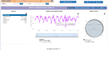
Weather and solar resource evaluation
Maximum ambient temperature = 23°C
Minimum ambient temperature = 2°C
Maximum indoor temperature = 20°C
Minimum indoor temperature = 10°C

Retrieving PVGIS monthly insolation data.
Retrieving PVGIS monthly insolation data.

Retrieving PVGIS weather data.
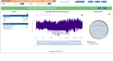
Retrieving PVGIS weather data.


Load and solar resource comparison
Step 1: Determine monthly ratio of energy demand to solar resource
| Month | Average monthly insolation | Total average daily energy demand | Ratio |
|---|---|---|---|
| January | 193.85 kWh/m² | 140 Wh | .722 |
| February | 162.2 kWh/m² | 140 Wh | .86 |
| March | 179.81 kWh/m² | 140 Wh | .78 |
| April | 174.98 kWh/m² | 140 Wh | .8 |
| May | 214.31 kWh/m² | 140 Wh | .65 |
| June | 200.05 kWh/m² | 140 Wh | .7 |
| July | 210.35 kWh/m² | 140 Wh | .67 |
| August | 229.96 kWh/m² | 140 Wh | .61 |
| September | 126.87 kWh/m² | 140 Wh | 1.1 |
| October | 214.82 kWh/m² | 140 Wh | .65 |
| November | 212.91 kWh/m² | 140 Wh | .66 |
| December | 176.98 kWh/m² | 140 Wh | .79 |
- Month: The month of the year.
- Average monthly insolation: Solar resource data obtained for the location from Weather and solar resource evaluation.
- Total average daily energy demand for the month from the load evaluation.
- Ratio = Total average daily energy demand ÷ Average monthly insolation
Step 2: Determine design values
| Design daily insolation | = Average monthly insolation from month with the highest ratio ÷ 30 |
|---|---|
| = 126.87 kWh/m² ÷ 30 = 4.23 kWh/m² |
| Design daily watt-hours required | = Total average daily energy demand from month with the highest ratio |
|---|---|
| = 140 Wh |
Design parameters
DC system voltage = 12 V
- The system, based upon the load evaluation, will be relatively small. A 12 V system makes the most sense.
Irradiance safety parameter = 1.25
- The irradiance safety parameter is always the same.
Continuous duty safety parameter = 1.25
- The continuous duty safety parameter is always the same.
Low voltage disconnect parameter = 11.5 V
- A simple charge controller with a pre-programmed low voltage disconnect will be used.
Energy storage sizing and selection
Step 1: Determine depth of discharge parameter
For this project a depth of discharge of .4 (40%) is a good compromise.
- Depth of discharge = .4
Step 2: Determine days of autonomy parameter
The home is used daily and providing lighting is very important, but at the same time the budget for the project is limited. The users are willing to adjust their consumption during periods of poor weather according to the state of charge of the energy storage system.
- Days of autonomy = 2
Step 3: Determine battery temperature correction factor
The minimum indoor temperature was determined to be 10°C. An AGM battery will be used to avoid regular maintenance.
- Battery temperature correction factor = 1.08
Correction factors for various battery types:[1]
| Temperature | FLA | AGM | Gel |
|---|---|---|---|
| 25°C | 1.00 | 1.00 | 1.00 |
| 20°C | 1.06 | 1.03 | 1.04 |
| 15°C | 1.13 | 1.05 | 1.07 |
| 10°C | 1.19 | 1.08 | 1.11 |
| 5°C | 1.29 | 1.14 | 1.18 |
| 0°C | 1.39 | 1.20 | 1.25 |
| -5°C | 1.55 | 1.28 | 1.34 |
| -10°C | 1.70 | 1.35 | 1.42 |
Step 4: Calculate total Ah required
| Total Ah required | = Average daily Watt-hours required ÷ DC system voltage × Battery temperature correction factor (Step 3) × Days of autonomy parameter (Step 2) ÷ Depth of discharge parameter (Step 1) |
|---|---|
| = 140 Wh ÷ 12 V × 1.08 × 2 days ÷ .4 = 43 Ah |
One MK Deka 12V 55 Ah AGM battery will provide enough storage capacity. Specifications sheet
- Specifications:
- Battery type: AGM
- Nominal voltage: 12 V
- C/20 rated capacity: 55 Ah
Step 5: Calculate number of batteries in series
| Batteries in series | = DC system voltage ÷ Chosen battery voltage |
|---|---|
| = 12 V ÷ 12 V | |
| = 1 battery |
Step 6: Calculate number of parallel battery circuits
| Parallel battery circuits | = Total Ah required (Step 4) ÷ Chosen battery Ah rating |
|---|---|
| = 43 Ah ÷ 55 Ah = .78 | |
| = Round up to 1 parallel battery circuit (1 battery) |
Step 7: Calculate final Ah capacity
| Final Ah capacity | = Parallel battery circuit (Step 6) × Chosen battery Ah rating |
|---|---|
| = 1 parallel battery circuit × 55 Ah = 55Ah |
Minimum PV source size
Step 1: Deteremine PV source loss parameters
The PV module(s) will be mounted on a pole mount system.
- Module degradation parameter = .94
- Shading loss parameter = .95
- Soiling loss parameter = .97
- Wiring loss parameter = .96
- Module mismatch parameter = 1
- Mounting system temperature adder = 20°C for a pole mount
- Temperature coefficient of max power %/°C = -.48%/°C
| PV source temperature loss parameter | = 1 + (Maximum ambient temperature + Mounting system temperature adder - 25°C) x Temperature coefficient of max power %/°C ÷ 100 |
|---|---|
| = 1 + (23°C + 20°C - 25°C) x -.48%/°C ÷ 100 = .91 |
| Total PV source loss parameter | = Module degradation parameter × Shading loss parameter × Soiling loss parameter × Wiring loss parameter × Module mismatch parameter × PV source temperature loss parameter |
|---|---|
| = .94 × .95 × .97 × .96 × 1 × .91 = .76 |
Step 2: Charge controller efficiency parameter
All charge controllers lose a certain percentage of all energy that is produced as heat as it is transferred to the energy storage system and loads. For both PWM and MPPT charge controllers a value of .98 (98% efficient) can be used.
Step 3: Energy storage efficiency parameter
The system will use an AGM battery, which is a VRLA battery.
- Valve-regulated lead acid (VRLA) battery efficiency = .85 (85% efficient)
Step 4: Deteremine minimum size of the PV source
| Minimum PV source size | = Design daily watt-hours required ÷ Design daily insolation ÷ Total PV source loss parameter (Step 1) ÷ Charge controller efficiency parameter (Step 2) ÷ Energy storage efficiency parameter (Step 3) |
|---|---|
| = 140 Wh ÷ 4.23 kWh/m² ÷ .76 ÷ .98 ÷ .85 = 52 W |
Step 5: Determine charge controller type
A PWM charge controller is a reliable, low-cost option for a small system like this.
PWM charge controller sizing and selection
Step 1: Determine PV module power rating
The chosen DC system voltage limits the choices of modules and configurations that are possible with a PWM charge controller. A 12 volt system requires 1 × 36-cell module per string. The minimum size was determined to be 52 W.
A Dasol 80 W, 36-cell polycrystalline PV module will be used for the design. Specifications sheet
Module specifications:
- Power = 80 W
- Open circuit voltage (Voc) = 22.3 V
- Short circuit current (Isc) = 4.85 A
- Max power voltage (Vmp) = 18.0 V
- Max power current (Imp) = 4.44 A
- Temperature coefficient of open circuit voltage (TkVoc) = -.36 %/°C
- Temperature coefficient of max power (TkPmp) = Not available.
| PV module power rating | = 80 W |
|---|
| Number of modules in series | = 1 module |
|---|
Step 2: Determine proposed module configuration
This calculation will give a minimum number of PV modules - the result should always be rounded up. Different modules sizes and configurations can be explored to find the optimal design.
| Minimum number of PV modules | = Minimum PV source size ÷ PV module power rating (Step 1) |
|---|---|
| = 52 W ÷ 80 W = .65 | |
| = 1 × 80 W module. |
| Minimum number of PV source circuits | = Minimum number of PV modules ÷ Number of modules in series (Step 1) |
|---|---|
| = 1 ÷ 1 = 1 |
Step 3: Verify excess production
| Proposed PV source low insolation production | = PV module power rating (Step 1) × Minimum number of PV modules (Step 2) × Total PV source loss parameter × Design daily insolation × Charge controller efficiency parameter × Energy storage efficiency parameter |
|---|---|
| = 80 W × 1 × .76 × 4.23 kWh/m² × .98 × .85 = 214 Wh |
| Daily excess production in Ah | = (Proposed PV source low insolation production - Design daily watt-hours required) ÷ DC system voltage |
|---|---|
| = (214 Wh - 140 Wh) ÷ 12 volts = 6.2 Ah |
| Ah used at full depth of discharge | = Final Ah capacity × Depth of discharge parameter |
|---|---|
| = 55Ah × .5 = 27.5 Ah |
| Time to reach full state of charge | = Ah used at full depth of discharge ÷ Daily excess production in Ah |
|---|---|
| = 27.5 Ah ÷ 6.2 Ah = 4.4 days |
The battery will be able to reach full state of charge while using loads in 4.4 days, which is less than the maximum of 7 days. The design is okay.
Step 4: Verify charging current
This system will use an AGM battery, so that charge current from the PV source should be between .05 (5%) and .2 (20%) of its C/20 rating.
It is necessary to check the minimum required charge current against the available charge current from the proposed PV source power rating.
| Available charging current | = Maximum power current (Imp) × Minimum number of PV source circuits |
|---|---|
| = 4.4 A × 1 = 4.4 A |
| Percentage of C/20 rate | = Available charging current ÷ Final Ah capacity |
|---|---|
| = 4.4 A ÷ 55 Ah = .08 |
The PV source can supply .08 (8%) of the C/20 current rating of the energy storage system, which is more than .05 (5%) and less than .2 (20%). The PV source configuration is okay.
Step 5: Determine final number of PV modules
Determine a final number of modules and a PV source circuit configuration that can meet the requirements of Step 1, Step 2, Step 3, and Step 4.
| Final number of PV modules | = 1 |
|---|
| Final number of PV modules in series | = 1 |
|---|
| Final number of PV source circuits | = 1 |
|---|
Step 6: Total PV source current
This calculation will give a minimum current rating to use as a basis for selecting the charge controller. The Isc rating of the PV module can be found on its specifications sheet.
| Total PV source current | = Final number of PV source circuits (Step 5) × Isc rating of chosen module (Step 1) × Irradiance safety parameter |
|---|---|
| = 1 × 4.85 A × 1.25 = 6.1 A |
Step 7: Select a charge controller
The final chosen charge controller should:
- Function at the DC system voltage.
- The charge controller(s) should have a total current rating that is larger than the minimum current rating (Step 6).
A Morningstar SHS-10 PWM charge controller will be used. Specifications sheet Multi-lingual user manual
- Specifications:
- Charge controller type: PWM
- Nominal output voltage: 12 V
- Maximum current rating: 10 A
The result of the following equation should always be rounded up.
| Number of charge controllers | = Total PV source current (Step 6) ÷ Chosen charge controller current rating |
|---|---|
| = 6.1 A ÷ 10 A = .61 = 1 (round up to 1 charge controller) |
Step 8: Determine final PV source power rating
| PV source power rating | = PV module power rating (Step 1) × Final number of PV modules (Step 5) |
|---|---|
| = 80 W × 1 = 80 W |
Step 9: Verify PV source and charge controller compatability
PWM charge controllers often have a maximum PV source power rating in watts that limits the size of the PV source. Verify that the maximum PV source power rating is greater than the final PV source power rating. If it is not, the charge controller size needs to be increased.
| PV source and charge controller compatability | = Final PV source power rating must be less than the maximum PV source power rating of the charge controller |
|---|---|
| = 80 W PV source is less than 170 W maximum input power rating of charge controller |
The PV source and charge controller are compatible.
Wire, overcurrent protection, and disconnect sizing and selection
The chosen wire for a circuit must meet the requirements set out in each phase of this process. The wire size must be increased if it fails to meet any of these phases and then the process must be performed again with the new wire size.
PV source circuit
Phase 1: Maximum circuit current
| Maximum circuit current | = PV module Isc × Irradiance safety parameter |
|---|---|
| = 4.85 A × 1.25 = 6.1 A |
Phase 2: Wire ampacity
There will only be two current-carrying conductors in the conduit. The maximum ambient temperature 23°C. 90°C wet/dry rated PV wire will be used for this circuit.
The minimum wire size for a circuit can be using the following steps:
- Determine the ambient temperature correction factor based upon the maximum ambient temperature using the ambient temperature correction factor table. The ambient temperature correction factor for this circuit is 1.05 because it is a 90°C wet/dry rated wire with a maximum ambient temperature of 23°C.
- Determine the conduit fill correction factor based upon the number of number of conductors in the conduit using the conduit fill correction factor table There will only be two current-carrying conductors in the conduit, so the conduit correction fill factor is 1.
- Determine the total wire correction parameter based upon the smaller of: the Ambient temperature correction multiplied by the Conduit fill correction factor or .8 (a safety factor from the US National Electrical code).
- Determine minimum wire ampacity. Divide the maximum circuit current (Phase 1) by the total wire correction factor (Step 3)
- Select a wire size with a maximum rated ampacity equal to or above the minimum wire ampacity calculated in the previous step using the allowable wire ampacity table. A 4 mm² / 12 AWG, 90°C wet/dry rated PV wire with an ampacity rating of 25 A will be used for this circuit as this is a commonly used wire type for a circuit of this type. 25 A is larger than the required 7.6 A ampacity.
| Total wire correction parameter | = Smaller of (Ambient temperature correction factor × Conduit fill correction factor) or .8 |
|---|---|
| = Smaller of (1.05 × 1) or .8 = .8 |
| Minimum wire ampacity | = Maximum circuit current (Phase 1) ÷ Total wire correction parameter (Step 3) |
|---|---|
| = 6.1 A ÷ .8 = 7.6 A |
Phase 3: Overcurrent protection and disconnects
This circuit, since it only has 1 PV module, does not require an OCPD, but one will be located near the PV equipment to provide a PV power source disconnect.
The appropriate overcurrent protection device size can be determined by:
- Determine the minimum size
- A standard 10 A DC breaker will be used. This breaker is larger than the required minimum OCPD size and smaller than the rated 25 A ampacity of the wire that it will protect. The PV source is current limited and the wire is sized to handle the maximum current, therefore it is not necessary to verify the OCPD size.
| Minimum OCPD size | = Maximum circuit current (Phase 1) × 1.25 |
|---|---|
| = 6.1 A × 1.25 = 7.6 A |
The OCPD size is okay.
Phase 4: Voltage drop
If the voltage drop for the wire chosen in Phase 2 for a particular circuit is not within the recommended values, then using a larger sized wire should be considered. Increasing the wire size will not affect any other part of this process; the calculated OCPD size can remain the same.
This circuit will be 6 meters long one-way. It is 4 mm² / 12 AWG, wire with a resistance value in (Ω/Km) of 6.73 Ω. It is recommended that the voltage drop between the PV source and the charge controller be kept below 3%.
| PV source circuit current | = Max power current of the PV module |
|---|---|
| = 4.44 A |
| PV source circuit nominal voltage | = Number of PV modules in series × Max power voltage of the PV module |
|---|---|
| = 18 V × 1 = 18 V |
| Voltage drop | = 2 x Circuit current x One-way circuit length (m) x Resistance (Ω/Km) ÷ 1000 |
|---|---|
| = 2 × 4.44 A × 6m × 6.73 Ω ÷ 1000 = .36 V |
| Percentage voltage drop | = Voltage drop ÷ nominal circuit voltage x 100 |
|---|---|
| = .36 V ÷ 18 V × 100 = 2% |
2% voltage drop for this circuit is acceptable. The wire size is okay.
Charge controller output circuit/battery circuit
This same size wire will be used from the charge controller to the battery with one overcurrent protection device which will also serve as a power source disconnect.
Phase 1: Maximum circuit current
| Maximum circuit current | = Current rating of the charge controller |
|---|---|
| = 10 A |
Phase 2: Wire ampacity
There will only be two current-carrying conductors in the conduit. The maximum indoor temperature 20°C. 75° wet / 90°C dry rated wire will be used for this circuit.
The minimum wire size for a circuit can be using the following steps:
- Determine the ambient temperature correction factor based upon the maximum ambient temperature using the ambient temperature correction factor table. The ambient temperature correction factor for this circuit is 1.11 because it is a 75° wet / 90°C dry rated wire with a maximum indoor temperature of 20°C.
- Determine the conduit fill correction factor based upon the number of number of conductors in the conduit using the conduit fill correction factor table There will only be two current-carrying conductors in the conduit, so the conduit correction fill factor is 1.
- Determine the total wire correction parameter based upon the Ambient temperature correction multiplied by the Conduit fill correction factor
- Determine minimum wire ampacity. Divide the maximum circuit current (Phase 1) by the total wire correction factor (Step 3)
- Select a wire size with a maximum rated ampacity equal to or above the minimum wire ampacity calculated in the previous step using the allowable wire ampacity table. A 4 mm² / 12 AWG, 75° wet / 90°C dry rated wire with an ampacity rating of 25 A will be used for this circuit as this is a commonly used wire type for a circuit of this type. 25 A is larger than the required 9.0 A ampacity.
| Total wire correction parameter | = Ambient temperature correction factor × Conduit fill correction factor |
|---|---|
| = 1.11 × 1 = 1.11 |
| Minimum wire ampacity | = Maximum circuit current (Phase 1) ÷ Total wire correction parameter (Step 3) |
|---|---|
| = 10 A ÷ 1.11 = 9.0 A |
Phase 3: Overcurrent protection and disconnects
This circuit requires an OCPD/disconnect as it is connected directly to the battery which is a power source. An OCPD size should be chosen from the list of standard OCPD sizes. If the current rating of the chosen OCPD size is larger than the maximum OCPD size under conditions of use, then the wire size must be increased the next size.
The appropriate overcurrent protection device size can be determined by:
- Determine the minimum size
- A standard 15 A DC breaker will be used. This breaker is larger than the required minimum OCPD size, but smaller than the 25 A rated ampacity of the wire that it will protect.
- Verify that the chosen OCPD size from Step 2 will protect the wire size chosen in Phase 2 from excessive current under the conditions of use. The current rating of the chosen OCPD size (Step 2) must be less than the calculated maximum current under conditions of use unless the calculated maximum current under conditions of use is between standard OCPD values, in this case the next largest OCPD size is used from the list of standard OCPD sizes. If the current rating of the chosen OCPD size is larger than the maximum OCPD size under conditions of use, then the wire size must be increased until it passes this test.
Maximum current under conditions of use = Wire ampacity from allowable wire ampacity table × Total wire correction parameter (Phase 2). = 25 A × 1.11 = 27.75 A Determine the maximum OCPD size under conditions of use.
Maximum OCPD size under conditions of use = Can be equal to the maximum current under conditions of use. If between standard OCPD sizes, the next largest OCPD is used. Except for the following wire sizes: 15 A maximum for 2.5 mm² / 14 AWG. 20 A maximum for 4 mm² / 12 AWG. 30 A maximum for 6 mm² / 10 AWG. = 20 A OCPD Verify OCPD under conditions of use = The current rating of the chosen OCPD (Step 2) must be less than or equal to the maximum OCPD size under conditions of use = 15 A OCPD is less than 20 A OCPD maximum size
| Minimum OCPD size | = Maximum circuit current (Phase 1) × 1.25 |
|---|---|
| = 10 A × 1.25 = 12.5 A |
The OCPD and wire size are okay.
Phase 4: Voltage drop
If the voltage drop for the wire chosen in Phase 2 for a particular circuit is not within the recommended values, then using a larger sized wire should be considered. Increasing the wire size will not affect any other part of this process; the calculated OCPD size can remain the same.
This circuit will be 1.5 meters long one-way. It is 4 mm² / 12 AWG, wire with a resistance value in (Ω/Km) of 6.73 Ω. It is recommended that the voltage drop between the charge controller and the energy storage system be kept below 1.5%. The circuit current is the Imp of the PV module: 4.44 A. The nominal circuit voltage is the DC system voltage: 12 V.
| Voltage drop | = 2 x Circuit current x One-way circuit length (m) x Resistance (Ω/Km) ÷ 1000 |
|---|---|
| = 2 × 4.44 A × 1.5m × 6.73 Ω ÷ 1000 = .09 V |
| Percentage voltage drop | = Voltage drop ÷ Nominal circuit voltage voltage x 100 |
|---|---|
| = .09 V ÷ 12 V × 100 = .75% |
.75% voltage drop for this circuit is acceptable. The wire size is okay.
Charge controller load circuit
Phase 1: Maximum circuit current
| Maximum circuit current | = Current rating of the charge controller lighting/load circuit |
|---|---|
| = 10 A |
Phase 2: Wire ampacity
There will only be two current-carrying conductors in the conduit. The maximum indoor temperature 20°C. 75° wet / 90°C dry rated wire will be used for this circuit.
The minimum wire size for a circuit can be using the following steps:
- Determine the ambient temperature correction factor based upon the maximum ambient temperature using the ambient temperature correction factor table. The ambient temperature correction factor for this circuit is 1.11 because it is a 75° wet / 90°C dry rated wire with a maximum indoor temperature of 20°C.
- Determine the conduit fill correction factor based upon the number of number of conductors in the conduit using the conduit fill correction factor table There will only be two current-carrying conductors in the conduit, so the conduit correction fill factor is 1.
- Determine the total wire correction parameter based upon the Ambient temperature correction multiplied by the Conduit fill correction factor
- Determine minimum wire ampacity. Divide the maximum circuit current (Phase 1) by the total wire correction factor (Step 3)
- Select a wire size with a maximum rated ampacity equal to or above the minimum wire ampacity calculated in the previous step using the allowable wire ampacity table. A 4 mm² / 12 AWG, 75° wet / 90°C dry rated wire with an ampacity rating of 25 A will be used for this circuit as this is a commonly used wire type for a circuit of this type. 25 A is larger than the required 9.0 A ampacity.
| Total wire correction parameter | = Ambient temperature correction factor × Conduit fill correction factor |
|---|---|
| = 1.11 × 1 = 1.11 |
| Minimum wire ampacity | = Maximum circuit current (Phase 1) ÷ Total wire correction parameter (Step 3) |
|---|---|
| = 10 A ÷ 1.11 = 9.0 A |
Phase 3: Overcurrent protection and disconnects
This circuit does not require an OCPD if the available current is limited by another OCPD or the charge controller - in this case there is both a 15 A OCPD on the connection to the battery and the charge controller itself is current limited to 10 A - to a maximum current that is below the ampacity rating of the wire. It is necessary to check to make sure that the wire will be protected by the other OCPD under the conditions of use.
Verify that the nearest OCPD will protect the wire size chosen in Phase 2 from excessive current under the conditions of use. The current rating of the OCPD must be less than the calculated maximum current under conditions of use unless the calculated maximum current under conditions of use is between standard OCPD values, in this case the next largest OCPD size is used from the list of standard OCPD sizes. If the current rating of the chosen OCPD size is larger than the maximum OCPD size under conditions of use, then the wire size must be increased until it passes this test or an additional OCPD must be added to protect this circuit.
| Maximum current under conditions of use | = Wire ampacity from allowable wire ampacity table × Total wire correction parameter (Phase 2). |
|---|---|
| = 25 A × 1.11 = 27.8 A |
Determine the maximum OCPD size under conditions of use.
| Maximum OCPD size under conditions of use | = Can be equal to the maximum current under conditions of use. If between standard OCPD sizes, the next largest OCPD is used. Except for the following wire sizes: 15 A maximum for 2.5 mm² / 14 AWG. 20 A maximum for 4 mm² / 12 AWG. 30 A maximum for 6 mm² / 10 AWG. |
|---|---|
| = 20 A OCPD |
| Verify OCPD under conditions of use | = The current rating of the chosen OCPD (Step 2) must be less than or equal to the maximum OCPD size under conditions of use |
|---|---|
| = 15 A OCPD is less than the maximum 20 A OCPD size |
No additional OCPD is necessary
Phase 4: Voltage drop
If the voltage drop for the wire chosen in Phase 2 for a particular circuit is not within the recommended values, then using a larger sized wire should be considered. Increasing the wire size will not affect any other part of this process; the calculated OCPD size can remain the same.
This circuit will be .25 meters long one-way. It is 4 mm² / 12 AWG, wire with a resistance value in (Ω/Km) of 6.73 Ω. It is recommended that the voltage drop between the charge controller be kept below 5% for any lights and below 3% for any loads. The circuit current is the current required by The circuit nominal voltage is the Nominal circuit voltage is the DC system voltage: 12 V.
| Charge controller load circuit current | = Power rating of all DC loads ÷ Nominal circuit voltage |
|---|---|
| = 56 W ÷ 12 V = 4.67 A |
| Voltage drop | = 2 x Circuit current x One-way circuit length (m) x Resistance (Ω/Km) ÷ 1000 |
|---|---|
| = 2 × 4.67 A × .25m × 6.73 Ω ÷ 1000 = .016 V |
| Percentage voltage drop | = Voltage drop ÷ Nominal circuit voltage x 100 |
|---|---|
| = .016 V ÷ 12 V × 100 = .13% |
.13% voltage drop for this circuit is acceptable. The wire size is okay.
DC branch circuit example
All DC branch circuits can be calculated in the same way as this example. This circuit has 3 × 5 W light bulbs.
Phase 1: Maximum circuit current
| Maximum circuit current | = Power rating of all DC loads on the circuit ÷ Nominal circuit voltage |
|---|---|
| = (3 × 5 W) ÷ 12 V = 1.25 A |
Phase 2: Wire ampacity
There will only be two current-carrying conductors in the conduit. The maximum indoor temperature 20°C. 75° wet / 90°C dry rated wire will be used for this circuit.
The minimum wire size for a circuit can be using the following steps:
- Determine the ambient temperature correction factor based upon the maximum ambient temperature using the ambient temperature correction factor table. The ambient temperature correction factor for this circuit is 1.11 because it is a 75° wet / 90°C dry rated wire with a maximum indoor temperature of 20°C.
- Determine the conduit fill correction factor based upon the number of number of conductors in the conduit using the conduit fill correction factor table There will only be two current-carrying conductors in the conduit, so the conduit correction fill factor is 1.
- Determine the total wire correction parameter based upon the Ambient temperature correction multiplied by the Conduit fill correction factor
- Determine minimum wire ampacity. Divide the maximum circuit current (Phase 1) by the total wire correction factor (Step 3)
- Select a wire size with a maximum rated ampacity equal to or above the minimum wire ampacity calculated in the previous step using the allowable wire ampacity table. A 2.5 mm² / 14 AWG, 75° wet / 90°C dry rated wire with an ampacity rating of 20 A will be used for this circuit as this is a commonly used wire type for a circuit of this type. 20 A is larger than the required 1.56 A ampacity.
| Total wire correction parameter | = Ambient temperature correction factor × Conduit fill correction factor |
|---|---|
| = 1.11 × 1 = 1.11 |
| Minimum wire ampacity | = Maximum circuit current (Phase 1) ÷ Total wire correction parameter (Step 3) |
|---|---|
| = 1.25 A ÷ 1.11 = 1.13 A |
Phase 3: Overcurrent protection and disconnects
This circuit does not require an OCPD if the available current is limited by another OCPD or the charge controller - in this case there is both a 15 A OCPD on the connection to the battery and the charge controller itself is current limited to 10 A - to a maximum current that is below the ampacity rating of the wire. It is necessary to check to make sure that the wire will be protected by the other OCPD under the conditions of use.
Verify that the nearest OCPD will protect the wire size chosen in Phase 2 from excessive current under the conditions of use. The current rating of the OCPD must be less than the calculated maximum current under conditions of use unless the calculated maximum current under conditions of use is between standard OCPD values, in this case the next largest OCPD size is used from the list of standard OCPD sizes. If the current rating of the chosen OCPD size is larger than the maximum OCPD size under conditions of use, then the wire size must be increased until it passes this test or an additional OCPD must be added to protect this circuit.
| Maximum current under conditions of use | = Wire ampacity from allowable wire ampacity table × Total wire correction parameter (Phase 2). |
|---|---|
| = 20 A × 1.11 = 22.2 A |
Determine the maximum OCPD size under conditions of use.
| Maximum OCPD size under conditions of use | = Can be equal to the maximum current under conditions of use. If between standard OCPD sizes, the next largest OCPD is used. Except for the following wire sizes: 15 A maximum for 2.5 mm² / 14 AWG. 20 A maximum for 4 mm² / 12 AWG. 30 A maximum for 6 mm² / 10 AWG. |
|---|---|
| = 15 A OCPD |
| Verify OCPD under conditions of use | = The current rating of the chosen OCPD (Step 2) must be less than or equal to the maximum OCPD size under conditions of use |
|---|---|
| = 15 A OCPD is equal to the maximum 15 A OCPD size |
No additional OCPD is necessary
Phase 4: Voltage drop
If the voltage drop for the wire chosen in Phase 2 for a particular circuit is not within the recommended values, then using a larger sized wire should be considered. Increasing the wire size will not affect any other part of this process; the calculated OCPD size can remain the same.
This circuit will be 8m meters long one-way. It is 2.5 mm² / 14 AWG, wire with a resistance value in (Ω/Km) of 10.7 Ω. It is recommended that the voltage drop between the charge controller be kept below 5% for any lights and below 3% for any loads. The circuit current is operating current and voltage of the charge controller output. Current is total current required by all of the loads on the circuit (same as calculated in Phase 1). Operating voltage is nominal voltage of the system: 12 V.
| Voltage drop | = 2 x Circuit current x One-way circuit length (m) x Resistance (Ω/Km) ÷ 1000 |
|---|---|
| = 2 × 1.25 A × 8m × 10.7 Ω ÷ 1000 = .21 V |
| Percentage voltage drop | = Voltage drop ÷ Circuit operating voltage x 100 |
|---|---|
| = .09 V ÷ 12 V × 100 = 1.75% |
1.75% voltage drop for this circuit is acceptable. The combined voltage drop of this circuit and the charge controller load circuit voltage drop is 1.88%, which is less than the recommended maximum of 3%. The wire size is okay.
Design summary

- DC nominal voltage: 12 V
- Mounting system: Pole mount
- Tilt angle: 14°
- Azimuth: 0°
Components
- PV module: Dasol WDS-A18-80 36-cell polycrystaline module Specifications sheet
- Charge controller: Morningstar SHS-10 PWM charge controller Specifications sheet Multi-lingual user manual
- Energy storage system: MK 8A22NF-DEKA 12V, 55Ah AGM battery Specifications sheet
Circuits
- PV source circuit: 4 mm² / 12 AWG, 90°C PV wire. 10 A breaker as a power source disconnect.
- Charge controller output circuit/energy storage circuit: 4 mm² / 12 AWG, 75° wet / 90°C dry rated wire. 15 A breaker as a power source disconnect.
- Charge controller load circuit: 4 mm² / 12 AWG, 75° wet / 90°C dry rated wire. No overcurrent protection device required.
- DC branch circuit: 2.5 mm² / 14 AWG, 75° wet / 90°C dry rated wire. No overcurrent protection device required.
Grounding system
- Grounding system: No grounding system due to cost and the simplicity of the system.
Notes/references
- ↑ Trojan Battery Company - Battery Sizing Guidelines https://www.trojanbattery.com/pdf/TRJN0168_BattSizeGuideFL.pdf