Detailed AC/DC system design
Location: Puerto Arturo, Madre de Dios, Peru
GPS coordinates: -12.48694444, -69.21305556
Altitude: 191 m
Grid voltage and frequency: 220 V at 60 Hz
Description:
A community building with lighting and AC power needs. The system is used all year long, but it is typically only used three to four times a week by community members for meetings, parties, or training sessions. Load usage is typically during the day. The community does not intend on adding any major appliances in the near future.
The system will use DC for lighting and AC for powering loads. DC is used for lighting so that the system continually provides light regardless of whether the inverter is turned on. As the building is used intermittently, the inverter can be turned off to reduce wear and to lessen the liklihood of an accident or damage from lightning.
The system has a DC system voltage of 24 V, so it will require a DC-DC converter in order to be able to provide 12 V for lighting circuits.

Photo of the building.

Location of the building.


Contents
- 1 Load evaluation
- 2 Weather and solar resource evaluation
- 3 Load and solar resource comparison
- 4 Design parameters
- 5 Energy storage sizing and selection
- 6 Minimum PV source size
- 7 PWM charge controller sizing and selection
- 7.1 Step 1: Determine PV module power rating
- 7.2 Step 2: Determine proposed module configuration
- 7.3 Step 3: Verify excess production
- 7.4 Step 4: Verify charging current
- 7.5 Step 5: Determine final number of PV modules
- 7.6 Step 6: Total PV source current
- 7.7 Step 7: Select a charge controller
- 7.8 Step 8: Determine final PV source power rating
- 7.9 Step 9: Verify PV source and charge controller compatability
- 8 DC-DC converter sizing and selection
- 9 Inverter sizing and selection
- 10 Wire, overcurrent protection, and disconnect sizing and selection
- 11 Grounding system sizing and selection
- 12 Design summary
- 13 Notes/references
Load evaluation
Although the system is used only one day a week, inputting 1 day a week of usage for the loads will lead to an undersized array and a poor system design. We will input 4 days a week to ensure that the PV source is still of a reasonable size.
DC load evaluation
Step 1: Fill out DC load chart
| April - September | October - March | ||||||||||
|---|---|---|---|---|---|---|---|---|---|---|---|
| # | Load | Quantity | Watts | Total watts | Duty cycle | Hours per day | Days per week | Average daily DC watt-hours | Hours per day | Days per week | Average daily DC watt-hours |
| 1 | LED light | 8 | 5 W | 40 W | 1 | 3 hours | 4 days | 69 Wh | 3 hours | 4 days | 69 Wh |
| 2 | Inverter | 1 | 7 W | 7 W | 1 | 3 hours | 4 days | 12 Wh | 5 hours | 4 days | 12 Wh |
- Load: The make and model or type of load.
- Quantity: The number of the particular load.
- Watts: The power rating in watts of the load.
- Total watts = Quantity × Watts
- Duty cycle = Rated or estimated duty cycle for the load. If the load has no duty cycle a value of 1 should be used. A load with a duty cycle of 20% would be inputted as .2
- Hours per day: The maximum number of hours the load(s) will be operated per day. If the load has a duty cycle 24 hours should be used.
- Days per week: The maximum number of days the load(s) will be operated per week.
- Average daily DC watt-hours = Total watts × Duty cycle × Hours per day × Days per week ÷ 7 days
Step 2: Determine DC energy demand
| Total average daily DC watt-hours (April - September) | = sum of Average daily DC watt-hours for all loads for April - September |
|---|---|
| = 81 Wh |
| Total average daily DC watt-hours (October - March) | = sum of Average daily DC watt-hours for all loads for October - March |
|---|---|
| = 81 Wh |
AC load evaluation
Step 1: Determine inverter efficiency
A conservative inverter efficiency value of .85 is going to be used.
| Inverter efficiency | .85 |
|---|
Step 2: Fill out AC load chart
| April - October | March - September | ||||||||||||||
|---|---|---|---|---|---|---|---|---|---|---|---|---|---|---|---|
| # | Load | Quantity | Watts | Total watts | Duty cycle | Surge factor | Surge watts | Power factor | Volt-amperes (VA) | Hours per day | Days per week | Average daily AC watt-hours | Hours per day | Days per week | Average daily AC watt-hours |
| 1 | Projector | 1 | 300 W | 300 W | 1 | 0 | 0 | .9 | 333 VA | 3 hours | 4 days | 605 Wh | 3 hours | 4 days | 605 Wh |
| 2 | Stereo | 1 | 30 W | 30 W | 1 | 0 | 0 | .9 | 33 VA | 3 hours | 4 days | 61 Wh | 3 hours | 4 days | 61 Wh |
| 3 | Cell phone | 5 | 5 W | 25 W | 1 | 0 | 0 | .9 | 28 VA | 1 hour | 4 days | 17 Wh | 1 hour | 4 days | 17 Wh |
- Load: The make and model or type of load.
- Quantity: The number of the particular load.
- Watts: The power rating in watts for the load.
- Total watts = Quantity × Watts
- Duty cycle = Rated or estimated duty cycle for the load. If the load has no duty cycle a value of 1 should be used. A load with a duty cycle of 20% would be inputted as .2
- Surge factor = Rated or estimated duty cycle for the load. Common values are between 3-5. If the load does not have a surge requirement a value of 0 should be used.
- Power factor = Rated or estimated power factor for the load.
- Volt-amperes (VA) = Total watts ÷ Power factor
- Hours per day: The maximum number of hours the load(s) will be operated per day. If the load has a duty cycle 24 hours should be used.
- Days per week: The maximum number of days the load(s) will be operated per week.
- Average daily AC Watt-hours = Total watts × Duty cycle ÷ Inverter efficiency (Step 1) × Hours per day × Days per week ÷ 7 days
Step 3: Deteremine AC energy demand
| Total average daily AC watt-hours (April - September) | = sum of Average daily AC watt-hours for all loads for April - September |
|---|---|
| = 682 Wh |
| Total average daily AC watt-hours (October - March) | = sum of Average daily AC watt-hours for all loads for October - March |
|---|---|
| = 682 Wh |
Step 4: Determine AC power demand
| Total VA | = sum of volt-amperes (VA) |
|---|---|
| = 394 VA |
| Total VA with surge watts | = sum of Surge watts for all loads + Total VA |
|---|---|
| = 394 VA |
Total average daily energy demand
The total energy demand for the system is the added Average daily DC-watt hours and Average daily AC watt-hours for each time period.
| Average daily watt-hours required (April - September) | = Total average daily DC watt-hours (April - October) + Total average daily AC watt-hours (April - September) |
|---|---|
| = 81 Wh + 682 Wh = 763 Wh |
| Average daily watt-hours required (April - September) | = Total average daily DC watt-hours (October - March) + Total average daily AC watt-hours (October - March) |
|---|---|
| = 81 Wh + 682 Wh = 763 Wh |
Weather and solar resource evaluation
Maximum ambient temperature = 35°C
Minimum ambient temperature = 15°C
Maximum indoor temperature = 30°C
Minimum indoor temperature = 20°C

Retrieving PVGIS monthly insolation data.
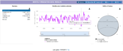
Retrieving PVGIS monthly insolation data.

Retrieving PVGIS weather data.
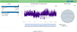
Retrieving PVGIS weather data.


Load and solar resource comparison
Step 1: Determine monthly ratio of energy demand to solar resource
| Month | Average monthly insolation | Total average daily energy demand | Ratio |
|---|---|---|---|
| January | 131.2 kWh/m² | 763 Wh | 5.81 |
| February | 110.5 kWh/m² | 763 Wh | 6.90 |
| March | 145.2 kWh/m² | 763 Wh | 5.25 |
| April | 143.5 kWh/m² | 763 Wh | 5.32 |
| May | 123.2 kWh/m² | 763 Wh | 6.19 |
| June | 132.8 kWh/m² | 763 Wh | 5.75 |
| July | 143.3 kWh/m² | 763 Wh | 5.32 |
| August | 167.6 kWh/m² | 763 Wh | 4.55 |
| September | 112.4 kWh/m² | 763 Wh | 6.79 |
| October | 147.0 kWh/m² | 763 Wh | 5.19 |
| November | 139.0 kWh/m² | 763 Wh | 5.49 |
| December | 134.3 kWh/m² | 763 Wh | 5.68 |
- Month: The month of the year.
- Average monthly insolation: Solar resource data obtained for the location from Weather and solar resource evaluation.
- Total average daily energy demand for the month from the load evaluation.
- Ratio = Total average daily energy demand ÷ Average monthly insolation
Step 2: Determine design values
| Design daily insolation | = Average monthly insolation from month with the highest ratio ÷ 30 |
|---|---|
| = 110.5 kWh/m² ÷ 30 = 3.7 kWh/m² |
| Design daily watt-hours required | = Total average daily energy demand from month with the highest ratio |
|---|---|
| = 763 Wh |
Design parameters
DC system voltage = 24 V
- This system will be built with a 24 volt nominal voltage in order to be able to use a 72-cell module. It could also easily be built as a 12 volt system.
Irradiance safety parameter = 1.25
- The irradiance safety parameter is always the same.
Continuous duty safety parameter = 1.25
- The continuous duty safety parameter is always the same.
Low voltage disconnect parameter = 22.2 V
- A simple charge controller with a pre-programmed low voltage disconnect will be used.
Energy storage sizing and selection
Step 1: Determine depth of discharge parameter
For this project a depth of discharge of .5 (50%) is a good compromise.
- Depth of discharge = .5
Step 2: Determine days of autonomy parameter
The building is used intermittently, but as the building serves an important need for the community it should still have at least 2 days of autonomy. The energy storage system size has already been reduced as all loads in the load evaluation were put in as only being used 4 days per week, but this calculation only works if the usage is spread out throughout the week. In this case, all of the usage will occurr during one day.
- Days of autonomy = 2
Step 3: Determine battery temperature correction factor
The minimum indoor temperature was determined to be 20°C. An AGM battery will be used to avoid regular maintenance.
- Battery temperature correction factor = 1.03
Correction factors for various battery types:[1]
| Temperature | FLA | AGM | Gel |
|---|---|---|---|
| 25°C | 1.00 | 1.00 | 1.00 |
| 20°C | 1.06 | 1.03 | 1.04 |
| 15°C | 1.13 | 1.05 | 1.07 |
| 10°C | 1.19 | 1.08 | 1.11 |
| 5°C | 1.29 | 1.14 | 1.18 |
| 0°C | 1.39 | 1.20 | 1.25 |
| -5°C | 1.55 | 1.28 | 1.34 |
| -10°C | 1.70 | 1.35 | 1.42 |
Step 4: Calculate total Ah required
| Total Ah required | = Average daily Watt-hours required ÷ DC system voltage × Battery temperature correction factor (Step 3) × Days of autonomy parameter (Step 2) ÷ Depth of discharge parameter (Step 1) |
|---|---|
| = 763 Wh ÷ 24 V × 1.03 × 2 days ÷ .5 = 131 Ah |
One series string of Trojan 12 V 135 Ah AGM batteries will provide sufficient storage capacity. Specifications sheet
- Specifications:
- Battery type: AGM
- Nominal voltage: 12 V
- C/20 rated capacity: 135 Ah
Step 5: Calculate number of batteries in series
A 12 V battery is ideal for a system of this size.
| Batteries in series | = DC system voltage ÷ Chosen battery voltage |
|---|---|
| = 24 V ÷ 12 V | |
| = 2 × 12 V batteries |
Step 6: Calculate number of parallel battery circuits
| Number of parallel battery circuits | = Total Ah required (Step 4) ÷ Chosen battery Ah rating |
|---|---|
| = 131 Ah ÷135 Ah = .97 | |
| = Round up to 1 parallel battery circuit (1 battery) |
Step 7: Calculate final Ah capacity
| Final Ah capacity | = Number of parallel battery circuits (Step 7) × Chosen battery Ah rating |
|---|---|
| = 2 parallel battery circuits × 135 Ah = 135 Ah |
Minimum PV source size
Step 1: Deteremine PV source loss parameters
The PV module(s) will be mounted on a pole mount system.
- Module degradation parameter = .94
- Shading loss parameter = .96
- Soiling loss parameter = .97
- Wiring loss parameter = .96
- Module mismatch parameter = 1
- Mounting system temperature adder = 20°C for a pole mount
- Temperature coefficient of max power %/°C = -.41%/°C
| PV source temperature loss parameter | = 1 + (Maximum ambient temperature + Mounting system temperature adder - 25°C) x Temperature coefficient of max power %/°C ÷ 100 |
|---|---|
| = 1 + (35°C + 20°C - 25°C) x -.41%/°C ÷ 100 = .88 |
| Total PV source loss parameter | = Module degradation parameter × Shading loss parameter × Soiling loss parameter × Wiring loss parameter × Module mismatch parameter × PV source temperature loss parameter |
|---|---|
| = .94 × .96 × .97 × .96 × 1 × .88 = .74 |
Step 2: Charge controller efficiency parameter
All charge controllers lose a certain percentage of all energy that is produced as heat as it is transferred to the energy storage system and loads. For both PWM and MPPT charge controllers a value of .98 (98% efficient) can be used.
Step 3: Energy storage efficiency parameter
The system will use an AGM battery, which is a VRLA battery.
- Valve-regulated lead acid (VRLA) battery efficiency = .85 (85% efficient)
Step 4: Deteremine minimum size of the PV source
| Minimum PV source size | = Design daily watt-hours required ÷ Design daily insolation ÷ Total PV source loss parameter (Step 1) ÷ Charge controller efficiency parameter (Step 2) ÷ Energy storage efficiency parameter (Step 3) |
|---|---|
| = 763 Wh ÷ 3.7 kWh/m² ÷ .74 ÷ .98 ÷ .85 = 335 W |
Step 5: Determine charge controller type
A PWM charge controller is a reliable, low-cost option for a small system like this.
PWM charge controller sizing and selection
Step 1: Determine PV module power rating
The chosen DC system voltage limits the choices of modules and configurations that are possible with a PWM charge controller. A 24 volt system requires 1 × 72-cell module per string. The minimum PV source size was determined to be 335 W.
A Canadian Solar 340W 72-cell polycrystalline PV module will be used for the design. Specifications sheet
| PV module power rating | = 340 W |
|---|
| Number of modules in series | = 1 module |
|---|
- Module specifications:
- Power = 340 W
- Open circuit voltage (Voc) = 46.2 V
- Short circuit current (Isc) = 9.48 A
- Max power voltage (Vmp) = 37.9 V
- Max power current (Imp) = 8.97 A
- Temperature coefficient of open circuit voltage (TkVoc) = -.31 %/°C
- Temperature coefficient of max power (TkPmp) = -.41 %/°C
Step 2: Determine proposed module configuration
This calculation will give a minimum number of PV modules - the result should always be rounded up. Different modules sizes and configurations can be explored to find the optimal design.
| Minimum number of PV modules | = Minimum PV source size ÷ PV module power rating (Step 1) |
|---|---|
| = 335 W ÷ 340 W = .99 | |
| = 1 × 340 W module |
| Minimum number of PV source circuits | = Minimum number of PV modules ÷ Number of modules in series (Step 1) |
|---|---|
| = 1 ÷ 1 = 1 |
Step 3: Verify excess production
This system is not used everyday, therefore it will generate sufficient energy on the days when it is not used to recharge the energy storage system.
Step 4: Verify charging current
This system will use an AGM battery, so that charge current from the PV source should be between .05 (5%) and .2 (20%) of its C/20 rating.
| Available charging current | = Maximum power current (Imp) × Minimum number of PV source circuits |
|---|---|
| = 9.05 A × 1 = 9.05 A |
| Percentage of C/20 rate | = Available charging current ÷ Final Ah capacity |
|---|---|
| = 9.05 A ÷ 135 Ah = .07 |
The PV source can supply .07 (7%) of the C/20 current rating of the energy storage system, which is more than .05 (5%) and less than .2 (20%). The PV source configuration is okay.
Step 5: Determine final number of PV modules
Determine a final number of modules and a PV source configuration that can meet the requirements of Step 1, Step 2, Step 3, and Step 4.
| Final number of PV modules | = 1 |
|---|
| Final number of PV modules in series | = 1 |
|---|
| Final number of PV source circuits | = 1 |
|---|
Step 6: Total PV source current
This calculation will give a minimum current rating to use as a basis for selecting the charge controller. The Isc rating of the PV module can be found on its specifications sheet.
| Total PV source current | = Final number of PV source circuits (Step 5) × Isc rating of chosen module (Step 1) × Irradiance safety parameter |
|---|---|
| = 1 × 9.62 A × 1.25 = 12 A |
Step 7: Select a charge controller
The final chosen charge controller should:
- Function at the DC system voltage.
- The charge controller(s) should have a total current rating that is larger than the minimum current rating (Step 6).
A Victron BlueSolar PWM-Pro 12/24 V 20 A charge controller will be used. Specifications sheet
- Specifications:
- Charge controller type: PWM
- Nominal output voltage: 12/24 V
- Maximum current rating: 20 A
The result of the following equation should always be rounded up.
| Number of charge controllers | = Total PV source current (Step 6) ÷ Chosen charge controller current rating |
|---|---|
| = 12 A ÷ 20 A = .6 = 1 (round up to 1 charge controller) |
Step 8: Determine final PV source power rating
| PV source power rating | = PV module power rating (Step 1) × Final number of PV modules (Step 5) |
|---|---|
| = 340 W × 1 = 340 W |
Step 9: Verify PV source and charge controller compatability
PWM charge controllers often have a maximum PV source power rating in watts that limits the size of the PV source. Verify that the maximum PV source power rating is greater than the final PV source power rating. If it is not, the charge controller size needs to be increased.
Victron does not have a maximum input power rating for this charge controller.
DC-DC converter sizing and selection
| Minimum current rating of the DC-DC converter | = Sum of all the power rating of all loads/lights ÷ Output voltage |
|---|---|
| = 40 W ÷ 12 V = 3.33 A |
A Samlex 12 A 24V-12V step down converter will be used. Specifications sheet
- Specifications:
- Input voltage: 20-32 V
- Output voltage: 13.6 V
- Maximum output current: 12 A
Inverter sizing and selection
The basic considerations for sizing and selecting an inverter are the following:
- The voltage must match the DC system voltage.
- The inverter should be able to meet the continuous power demand for all loads that will operate at the same time.
- The inverter should be able to meet the continuous power demand for all loads and the surge power demand for all loads that will operate at the same time.
Step 1: Determine the inverter continuous output rating
| Minimum inverter continuous duty rating | = Total VA |
|---|---|
| 394 VA |
Step 2: Determine minimum inverter surge rating
| Minimum inverter surge rating | = Total VA with surge watts |
|---|---|
| 394 VA |
Step 3: Determine final inverter continuous duty rating
The chosen inverter should:
- Match the DC system voltage.
- Have a larger continuous output rating than determined in Step 1.
- Have a larger surge rating than the determined in Step 2.
An Victron Phoenix 500 VA, 24 V inverter will be used. Specifications sheet
- Specifications:
- Nominal input voltage = 24 V
- Nominal output voltage = 220 V
- Nominal frequency = 60 Hz
- Continuous power rating (W) at 25°C = 400 W
- Continuous power rating (VA) at 25°C = 500 VA
- Peak/surge power (W) = 900 W
Step 4: Verify that maximum continuous current of inverter is acceptable
The energy storage system must be large enough to be able to supply the continuous current that the inverter requires. Using an inverter that is oversized relative to the energy storage system can damage the batteries and can cause the system to function improperly. It is recommended that the continous current required by the inverter not exceed .13 (13%) of the Final Ah capacity of the energy storage system for lead acid batteries and .2 (20%) for AGM batteries. If this value is exceeded, then the size of the energy storage system should be increased.
| Maximum recommended discharge current | = Final Ah capacity × (.13 for FLA and gel batteries, .2 for AGM batteries) |
|---|---|
| = 135 Ah × .2 = 27 A |
| Inverter continuous duty input current | = Final inverter continuous duty rating (Step 3) ÷ DC system voltage ÷ Inverter efficiency parameter |
|---|---|
| = 800 W ÷ 24 V ÷ .85 = 24.5 A |
The inverter at maximum capacity will draw less than .2 (20%) of the C/20 rate of the energy storage system. The inverter size is okay.
Wire, overcurrent protection, and disconnect sizing and selection
The chosen wire for a circuit must meet the requirements set out in each phase of this process. The wire size must be increased if it fails to meet any of these phases and then the process must be performed again with the new wire size.
PV source circuit
Phase 1: Maximum circuit current
| Maximum circuit current | = PV module Isc × Irradiance safety parameter |
|---|---|
| = 9.62 A × 1.25 = 12.03 A |
Phase 2: Wire ampacity
There will only be two current-carrying conductors in the conduit. The maximum ambient temperature 35°C. 90°C wet/dry rated PV wire will be used for this circuit.
The minimum wire size for a circuit can be using the following steps:
- Determine the ambient temperature correction factor based upon the maximum ambient temperature using the ambient temperature correction factor table. The ambient temperature correction factor for this circuit is .96 because it is a 90°C wet/dry rated wire with a maximum ambient temperature of 35°C.
- Determine the conduit fill correction factor based upon the number of number of conductors in the conduit using the conduit fill correction factor table There will only be two current-carrying conductors in the conduit, so the conduit correction fill factor is 1.
- Determine the total wire correction parameter based upon the smaller of: the Ambient temperature correction multiplied by the Conduit fill correction factor or .8 (a safety factor from the US National Electrical code).
- Determine minimum wire ampacity. Divide the maximum circuit current (Phase 1) by the total wire correction factor (Step 3)
- Select a wire size with a maximum rated ampacity equal to or above the minimum wire ampacity calculated in the previous step using the allowable wire ampacity table. A 4 mm² / 12 AWG, 90°C wet/dry rated PV wire with an ampacity rating of 25 A will be used for this circuit as this is a commonly used wire type for a circuit of this type. 25 A is larger than the required 15.04 A ampacity.
| Total wire correction parameter | = Smaller of (Ambient temperature correction factor × Conduit fill correction factor) or .8 |
|---|---|
| = Smaller of (.96 × 1) or .8 = .8 |
| Minimum wire ampacity | = Maximum circuit current (Phase 1) ÷ Total wire correction parameter (Step 3) |
|---|---|
| = 12.03 A ÷ .8 = 15.04 A |
Phase 3: Overcurrent protection and disconnects
This circuit, since it only has 1 PV module, does not require an OCPD, but one will be located near the PV equipment to provide a PV power source disconnect. The OCPD should be chosen using the list of standard OCPD sizes
The appropriate overcurrent protection device size can be determined by:
- Determine the minimum size
- A standard 15 A DC breaker will be used. This breaker is larger than the required minimum OCPD size, but smaller than the rated 30 A ampacity of the wire that it will protect.
- It is not necessary to verify that the OCPD will protect the chosen wire size as the PV source is current limited, therefore it cannot supply more current than the wire can handle.
| Minimum OCPD size | = Maximum circuit current (Phase 1) × 1.25 |
|---|---|
| = 12.03 A × 1.25 = 15.04 A |
Phase 4: Voltage drop
If the voltage drop for the wire chosen in Phase 2 for a particular circuit is not within the recommended values, then using a larger sized wire should be considered. Increasing the wire size will not affect any other part of this process; the calculated OCPD size can remain the same.
This circuit will be 6 meters long one-way. It is 4 mm² / 12 AWG, wire with a resistance value in (Ω/Km) of 6.73 Ω. It is recommended that the voltage drop between the PV source and the charge controller be kept below 3%. The circuit current is the Imp of the PV module: 9.02 A.
| PV source circuit current | = Max power current of the PV module |
|---|---|
| = 9.02 A |
| PV source circuit nominal voltage | = Number of PV modules in series × Max power voltage of the PV module |
|---|---|
| = 36 V × 1 = 36 V |
| Voltage drop | = 2 x Circuit current x One-way circuit length (m) x Resistance (Ω/Km) ÷ 1000 |
|---|---|
| = 2 × 9.02 A × 6m × 6.73 Ω ÷ 1000 = .73 V |
| Percentage voltage drop | = Voltage drop ÷ Nominal circuit voltage x 100 |
|---|---|
| = .73 V ÷ 36 V × 100 = 2% |
2% voltage drop for this circuit is acceptable. The wire size is okay.
Charge controller output circuit
The charge controller output circuit will be connected to common DC busbars (along with the inverter) that will be connected to the energy storage system by the energy storage circuit.
Phase 1: Maximum circuit current
| Maximum circuit current | = Current rating of the charge controller |
|---|---|
| = 20 A |
Phase 2: Wire ampacity
There will only be two current-carrying conductors in the conduit. The maximum indoor temperature 30°C. 75° wet / 90°C dry rated wire will be used for this circuit.
The minimum wire size for a circuit can be using the following steps:
- Determine the ambient temperature correction factor based upon the maximum ambient temperature using the ambient temperature correction factor table. The ambient temperature correction factor for this circuit is 1.00 because it is a 75° wet / 90°C dry rated wire with a maximum indoor temperature of 30°C.
- Determine the conduit fill correction factor based upon the number of number of conductors in the conduit using the conduit fill correction factor table There will only be two current-carrying conductors in the conduit, so the conduit correction fill factor is 1.
- Determine the total wire correction parameter based upon the Ambient temperature correction multiplied by the Conduit fill correction factor or .8 (a safety factor from the US National Electrical code).
- Determine minimum wire ampacity. Divide the maximum circuit current (Phase 1) by the total wire correction factor (Step 3)
- Select a wire size with a maximum rated ampacity equal to or above the minimum wire ampacity calculated in the previous step using the allowable wire ampacity table. A 6 mm² / 10 AWG, 75° wet / 90°C dry rated wire with an ampacity rating of 35 A will be used for this circuit as this is a commonly used wire type for a circuit of this type. 35 A is larger than the required 20 A ampacity.
| Total wire correction parameter | = Ambient temperature correction factor × Conduit fill correction factor |
|---|---|
| = 1.00 × 1 = 1 |
| Minimum wire ampacity | = Maximum circuit current (Phase 1) ÷ Total wire correction parameter (Step 3) |
|---|---|
| = 20 A ÷ 1 = 20 A |
Phase 3: Overcurrent protection and disconnects
This circuit will use an OCPD to protect it from excessive currents from the energy storage system and as an equipment disconnect, so that it can be disconnected from the energy storage system as needed.
The appropriate overcurrent protection device size can be determined by:
- Determine the minimum size
- A standard 25 A DC breaker will be used. This breaker is larger than the required minimum OCPD size, but smaller than the 35 A rated ampacity of the wire that it will protect.
- Verify that the chosen OCPD size from Step 2 will protect the wire size chosen in Phase 2 from excessive current under the conditions of use. The current rating of the chosen OCPD size (Step 2) must be less than the calculated maximum current under conditions of use unless the calculated maximum current under conditions of use is between standard OCPD values, in this case the next largest OCPD size is used from the list of standard OCPD sizes. If the current rating of the chosen OCPD size is larger than the maximum OCPD size under conditions of use, then the wire size must be increased until it passes this test.
Maximum current under conditions of use = Wire ampacity from allowable wire ampacity table × Total wire correction parameter (Phase 2). = 35 A × 1 = 35 A Determine the maximum OCPD size under conditions of use.
Maximum OCPD size under conditions of use = Can be equal to the maximum current under conditions of use. If between standard OCPD sizes, the next largest OCPD is used. Except for the following wire sizes: 15 A maximum for 2.5 mm² / 14 AWG. 20 A maximum for 4 mm² / 12 AWG,. 30 A maximum for 6 mm² / 10 AWG. = 30 A OCPD Verify OCPD under conditions of use = The current rating of the chosen OCPD (Step 2) must be less than or equal to the maximum OCPD size under conditions of use = 25 A OCPD is less than the maximum 30 A OCPD size
| Minimum OCPD size | = Maximum circuit current (Phase 1) × 1.25 |
|---|---|
| = 20 A × 1.25 = 25 A |
The OCPD and wire size are okay.
Phase 4: Voltage drop
If the voltage drop for the wire chosen in Phase 2 for a particular circuit is not within the recommended values, then using a larger sized wire should be considered. Increasing the wire size will not affect any other part of this process; the calculated OCPD size can remain the same.
This circuit will be .5 meters long one-way as it only needs to reach the DC busbars where the battery circuit is connected. It is 6 mm² / 10 AWG, wire with a resistance value in (Ω/Km) of 4.226 Ω. It is recommended that the voltage drop between the charge controller and energy storage system be less than 1.5%. The actual operating current of the charge controller will be the Imp of the PV module: 9.02 A. The nominal circuit voltage is the DC system voltage: 24 V.
| Voltage drop | = 2 x Circuit current x One-way circuit length (m) x Resistance (Ω/Km) ÷ 1000 |
|---|---|
| = 2 × 9.06 A × .5m × 4.226 Ω ÷ 1000 = .04 V |
| Percentage voltage drop | = Voltage drop ÷ Nominal circuit voltage voltage x 100 |
|---|---|
| = .04 V ÷ 24 V × 100 = .17% |
.17% voltage drop for this circuit is acceptable. The wire size is okay.
Charge controller load circuit
The charge controller output cirucit will be connected to a DC-DC converter with a 12 A current limit. A Samlex 12 A, 24V-12V step down converter will be used. Specifications sheet
Phase 1: Maximum circuit current
| Maximum circuit current | = Current rating of the DC-DC converter |
|---|---|
| = 12 A |
Phase 2: Wire ampacity
There will only be two current-carrying conductors in the conduit. The maximum indoor temperature 20°C. 75° wet / 90°C dry rated wire will be used for this circuit.
The minimum wire size for a circuit can be using the following steps:
- Determine the ambient temperature correction factor based upon the maximum ambient temperature using the ambient temperature correction factor table. The ambient temperature correction factor for this circuit is 1.00 because it is a 75° wet / 90°C dry rated wire with a maximum indoor temperature of 30°C.
- Determine the conduit fill correction factor based upon the number of number of conductors in the conduit using the conduit fill correction factor table There will only be two current-carrying conductors in the conduit, so the conduit correction fill factor is 1.
- Determine the total wire correction parameter based upon the Ambient temperature correction multiplied by the Conduit fill correction factor.
- Determine minimum wire ampacity. Divide the maximum circuit current (Phase 1) by the total wire correction factor (Step 3)
- Select a wire size with a maximum rated ampacity equal to or above the minimum wire ampacity calculated in the previous step using the allowable wire ampacity table. A 4 mm² / 12 AWG, 75° wet / 90°C dry rated wire with an ampacity rating of 25 A will be used for this circuit as this is a commonly used wire type for a circuit of this type. 25 A is larger than the required 12 A ampacity.
| Total wire correction parameter | = Ambient temperature correction factor × Conduit fill correction factor |
|---|---|
| = 1.00 × 1 = .8 |
| Minimum wire ampacity | = Maximum circuit current (Phase 1) ÷ Total wire correction parameter (Step 3) |
|---|---|
| = 12 A ÷ 1 = 12 A |
Phase 3: Overcurrent protection and disconnects
This circuit could function without an additional OCPD, but all wires would have to be increased in size to make sure that they are protected by the closest OCPD which is a 25 A breaker on the connection to between the charge controller and the common DC busbars. A breaker will be used here to enable smaller wires to be used.
The appropriate overcurrent protection device size can be determined by:
- Determine the minimum size
- A standard 15 A DC breaker will be used. This breaker is larger than the required minimum OCPD size, but smaller than the 30 A rated ampacity of the wire that it will protect.
- Verify that the chosen OCPD size from Step 2 will protect the wire size chosen in Phase 2 from excessive current under the conditions of use. The current rating of the chosen OCPD size (Step 2) must be less than the calculated maximum current under conditions of use unless the calculated maximum current under conditions of use is between standard OCPD values, in this case the next largest OCPD size is used from the list of standard OCPD sizes. If the current rating of the chosen OCPD size is larger than the maximum OCPD size under conditions of use, then the wire size must be increased until it passes this test.
Maximum current under conditions of use = Wire ampacity from allowable wire ampacity table × Total wire correction parameter (Phase 2). = 25 A × 1 = 25 A Determine the maximum OCPD size under conditions of use.
Maximum OCPD size under conditions of use = Can be equal to the maximum current under conditions of use. If between standard OCPD sizes, the next largest OCPD is used. Except for the following wire sizes: 15 A maximum for 2.5 mm² / 14 AWG. 20 A maximum for 4 mm² / 12 AWG. 30 A maximum for 6 mm² / 10 AWG. = 20 A OCPD Verify OCPD under conditions of use = The current rating of the chosen OCPD (Step 2) must be less than or equal to the maximum OCPD size under conditions of use = 15 A OCPD is less than the maximum 20 A OCPD size
| Minimum OCPD size | = Maximum circuit current (Phase 1) × 1.25 |
|---|---|
| = 12 A × 1.25 = 15 A |
The OCPD and wire size are okay.
Phase 4: Voltage drop
If the voltage drop for the wire chosen in Phase 2 for a particular circuit is not within the recommended values, then using a larger sized wire should be considered. Increasing the wire size will not affect any other part of this process; the calculated OCPD size can remain the same.
This circuit will be .25 meters long one-way. It is 4 mm² / 12 AWG, wire with a resistance value in (Ω/Km) of 6.73 Ω. It is recommended that the voltage drop between the charge controller and any lights be kept below 5%. The nominal circuit voltage is the DC system voltage: 24 V.
| Charge controller load circuit current | = Current rating of DC-DC converter |
|---|---|
| = 12 A |
| Voltage drop | = 2 x Circuit current x One-way circuit length (m) x Resistance (Ω/Km) ÷ 1000 |
|---|---|
| = 2 × 12 A × .25m × 6.73 Ω ÷ 1000 = .04 V |
| Percentage voltage drop | = Voltage drop ÷ Nominal circuit voltage x 100 |
|---|---|
| = .04 V ÷ 24 V × 100 = .17% |
.17% voltage drop for this circuit is acceptable. The wire size is okay.
DC branch circuit example
All DC branch circuits can be calculated in the same way as this example. A Samlex 12 A 24 V - 12 V step down converter is connected to the charge controller load circuit and will be used to provide 12 volt current to the lights in the building. Specifications sheet. This circuit has 3 × 5 W light bulbs.
Phase 1: Maximum circuit current
| Maximum circuit current | = Power rating of all DC loads on the circuit ÷ Nominal circuit voltage |
|---|---|
| = (3 × 5 W) ÷ 12 V = 1.25 A |
Phase 2: Wire ampacity
There will only be two current-carrying conductors in the conduit. The maximum indoor temperature 30°C. 75° wet / 90°C dry rated wire will be used for this circuit.
The minimum wire size for a circuit can be using the following steps:
- Determine the ambient temperature correction factor based upon the maximum ambient temperature using the ambient temperature correction factor table. The ambient temperature correction factor for this circuit is 1.00 because it is a 75° wet / 90°C dry rated wire with a maximum indoor temperature of 30°C.
- Determine the conduit fill correction factor based upon the number of number of conductors in the conduit using the conduit fill correction factor table There will only be two current-carrying conductors in the conduit, so the conduit correction fill factor is 1.
- Determine the total wire correction parameter based upon the Ambient temperature correction multiplied by the Conduit fill correction factor
- Determine minimum wire ampacity. Divide the maximum circuit current (Phase 1) by the total wire correction factor (Step 3)
- Select a wire size with a maximum rated ampacity equal to or above the minimum wire ampacity calculated in the previous step using the allowable wire ampacity table. A 2.5 mm² / 14 AWG, 75° wet / 90°C dry rated wire with an ampacity rating of 20 A will be used for this circuit as this is a commonly used wire type for a circuit of this type. 20 A is larger than the required 1.25 A ampacity.
| Total wire correction parameter | = Ambient temperature correction factor × Conduit fill correction factor |
|---|---|
| = 1.00 × 1 = 1 |
| Minimum wire ampacity | = Maximum circuit current (Phase 1) ÷ Total wire correction parameter (Step 3) |
|---|---|
| = 1.25 A ÷ 1 = 1.25 A |
Phase 3: Overcurrent protection and disconnects
This circuit does not require an OCPD if the available current is limited by another OCPD or a system components that is current limited. In this case, the maximum amount of current that the DC-DC converter can supply is 12 A.
Verify that the DC-DC converter will protect the wire size chosen in Phase 2 from excessive current under the conditions of use. The current rating of the DC-DC converter must be less than the calculated maximum current under conditions of use unless the calculated maximum current under conditions of use is between standard OCPD values, in this case the next largest OCPD size is used from the list of standard OCPD sizes. If the current rating of the chosen OCPD size is larger than the maximum OCPD size under conditions of use, then the wire size must be increased until it passes this test or an additional OCPD must be added to protect this circuit.
| Maximum current under conditions of use | = Wire ampacity from allowable wire ampacity table × Total wire correction parameter (Phase 2). |
|---|---|
| = 20 A × 1 = 20 A |
| Verify maximum fault current | = The current rating of the power source must be less thant he maximum current under conditions of use for the chosen wire |
|---|---|
| = 12 A rated DC-DC converter has a lower current rating than the 20 A maximum current for the wire under conditions of use. |
No additional OCPD is necessary
Phase 4: Voltage drop
If the voltage drop for the wire chosen in Phase 2 for a particular circuit is not within the recommended values, then using a larger sized wire should be considered. Increasing the wire size will not affect any other part of this process; the calculated OCPD size can remain the same.
This circuit will be 8m meters long one-way. It is 2.5 mm² / 14 AWG, wire with a resistance value in (Ω/Km) of 10.7 Ω. It is recommended that the voltage drop between the PV source and the charge controller below 1.5%. The circuit current is operating current and voltage of the charge controller output. Current is total current required by all of the loads on the circuit (same as calculated in Phase 1). Operating voltage is nominal voltage of the system: 12 V.
| Voltage drop | = 2 x Circuit current x One-way circuit length (m) x Resistance (Ω/Km) ÷ 1000 |
|---|---|
| = 2 × 1.25 A × 8m × 10.7 Ω ÷ 1000 = .21 V |
| Percentage voltage drop | = Voltage drop ÷ Circuit operating voltage x 100 |
|---|---|
| = .09 V ÷ 12 V × 100 = 1.75% |
1.75% voltage drop for this circuit is acceptable. The combined voltage drop of this circuit and the charge controller load circuit voltage drop is 1.92%, which is less than the recommended maximum of 3%. The wire size is okay.
Inverter input circuit
The charge inverter input circuit will be connected to common DC busbars (along with the charge controller) that will be connected to the energy storage system by the energy storage circuit.
Phase 1: Maximum circuit current
| Maximum circuit current | = Final inverter continuous duty rating ÷ Low voltage disconnect parameter ÷ Inverter efficiency parameter |
|---|---|
| = 500 W ÷ 22.2 V ÷ .85 = 27 A |
Phase 2: Wire ampacity
There will only be two current-carrying conductors in the conduit. The maximum indoor temperature 30°C. 75° wet/dry rated wire will be used for this circuit.
The minimum wire size for a circuit can be using the following steps:
- Determine the ambient temperature correction factor based upon the maximum ambient temperature using the ambient temperature correction factor table. The ambient temperature correction factor for this circuit is 1.00 because it is a 75°C wet/dry rated wire with a maximum indoor temperature of 30°C.
- Determine the conduit fill correction factor based upon the number of number of conductors in the conduit using the conduit fill correction factor table There will only be two current-carrying conductors in the conduit, so the conduit correction fill factor is 1.
- Determine the total wire correction parameter based upon the Ambient temperature correction multiplied by the Conduit fill correction factor.
- Determine minimum wire ampacity. Divide the maximum circuit current (Phase 1) by the total wire correction factor (Step 3)
- Select a wire size with a maximum rated ampacity equal to or above the minimum wire ampacity calculated in the previous step using the allowable wire ampacity table. A 10 mm² / 8 AWG, 75°C dry/wet rated wire with an ampacity rating of 50 A at 75°C will be used for this circuit as this is a commonly used wire type for a circuit of this type. 50 A is larger than the required 27 A ampacity.
| Total wire correction parameter | = Ambient temperature correction factor × Conduit fill correction factor |
|---|---|
| = 1.00 × 1 = 1 |
| Minimum wire ampacity | = Maximum circuit current (Phase 1) ÷ Total wire correction parameter (Step 3) |
|---|---|
| = 27 A ÷ 1 = 27 A |
Phase 3: Overcurrent protection and disconnects
This circuit will use an OCPD to protect it from excessive currents from the energy storage system and as an equipment disconnect, so that it can be disconnected from the energy storage system as needed.
The appropriate overcurrent protection device size can be determined by:
- Determine the minimum size
- A standard 35 A DC breaker will be used. This breaker is larger than the required minimum OCPD size and smaller than the 50 A rated ampacity of the wire that it will protect.
- Verify that the chosen OCPD size from Step 2 will protect the wire size chosen in Phase 2 from excessive current under the conditions of use. The current rating of the chosen OCPD size (Step 2) must be less than the calculated maximum current under conditions of use unless the calculated maximum current under conditions of use is between standard OCPD values, in this case the next largest OCPD size is used from the list of standard OCPD sizes. If the current rating of the chosen OCPD size is larger than the maximum OCPD size under conditions of use, then the wire size must be increased until it passes this test.
Maximum current under conditions of use = Wire ampacity from allowable wire ampacity table × Total wire correction parameter (Phase 2). = 50 A × 1 = 50 A Determine the maximum OCPD size under conditions of use.
Maximum OCPD size under conditions of use = Can be equal to the maximum current under conditions of use. If between standard OCPD sizes, the next largest OCPD is used. Except for the following wire sizes: 15 A maximum for 2.5 mm² / 14 AWG. 20 A maximum for 4 mm² / 12 AWG. 30 A maximum for 6 mm² / 10 AWG. = 50 A OCPD Verify OCPD under conditions of use = The current rating of the chosen OCPD (Step 2) must be less than or equal to the maximum OCPD size under conditions of use = 35 A OCPD is less than the maximum 50 A OCPD size
| Minimum OCPD size | = Maximum circuit current (Phase 1) × 1.25 |
|---|---|
| = 27 A × 1.25 = 33.75 A |
The OCPD and wire size are okay.
Phase 4: Voltage drop
If the voltage drop for the wire chosen in Phase 2 for a particular circuit is not within the recommended values, then using a larger sized wire should be considered. Increasing the wire size will not affect any other part of this process; the calculated OCPD size can remain the same.
This circuit will be .5 meters long one-way as it only needs to reach the DC busbars where the battery circuit is connected. It is 10 mm² / 8 AWG, wire with a resistance value in (Ω/Km) of 2.653 Ω. It is recommended that the voltage drop between the charge controller and energy storage system be less than 1.5%. The nominal circuit voltage is the DC system voltage: 24 V.
| Voltage drop | = 2 x Circuit current x One-way circuit length (m) x Resistance (Ω/Km) ÷ 1000 |
|---|---|
| = 2 × 27 A × .5m × 1.671 Ω ÷ 1000 = .05 V |
| Percentage voltage drop | = Voltage drop ÷ Nominal circuit voltage voltage x 100 |
|---|---|
| = .05 V ÷ 24 V × 100 = .21% |
.21% voltage drop for this circuit is acceptable. The wire size is okay.
Inverter output circuit
The inverter will limit the current that it can output. It is recommended that a residual current device (RCD) be installed on this circuit of the individual AC branch circuits. To minimize costs only one RCD will be installed on the inverter output circuit.
Phase 1: Maximum circuit current
| Maximum circuit current | = Final inverter continuous duty rating ÷ Inverter AC voltage |
|---|---|
| = 500 VA ÷ 220 V = 2.3 A |
Phase 2: Wire ampacity
There will only be two current-carrying conductors in the conduit. The maximum indoor temperature 30°C. 75° wet / 90°C dry rated wire will be used for this circuit.
The minimum wire size for a circuit can be using the following steps:
- Determine the ambient temperature correction factor based upon the maximum ambient temperature using the ambient temperature correction factor table. The ambient temperature correction factor for this circuit is 1.00 because it is a 75° wet / 90°C dry rated wire with a maximum indoor temperature of 30°C.
- Determine the conduit fill correction factor based upon the number of number of conductors in the conduit using the conduit fill correction factor table There will only be two current-carrying conductors in the conduit, so the conduit correction fill factor is 1.
- Determine the total wire correction parameter based upon the Ambient temperature correction multiplied by the Conduit fill correction factor
- Determine minimum wire ampacity. Divide the maximum circuit current (Phase 1) by the total wire correction factor (Step 3)
- Select a wire size with a maximum rated ampacity equal to or above the minimum wire ampacity calculated in the previous step using the allowable wire ampacity table. A 2.5 mm² / 14 AWG, 75° wet / 90°C dry rated wire with an ampacity rating of 20 A will be used for this circuit as this is a commonly used wire type for a circuit of this type. 20 A is larger than the required 2.9 A ampacity.
| Total wire correction parameter | = Ambient temperature correction factor × Conduit fill correction factor |
|---|---|
| = 1.00 × 1 = 1 |
| Minimum wire ampacity | = Maximum circuit current (Phase 1) ÷ Total wire correction parameter (Step 3) |
|---|---|
| = 2.3 A ÷ 1 = 2.3 A |
Phase 3: Overcurrent protection and disconnects
This circuit could function without an additional OCPD because it is current limited by the inverter, but a residual current device will be sized and added for safety.
The appropriate overcurrent protection device size can be determined by:
- Determine the minimum size
- A standard 4 A AC residual current device will be used. This breaker is larger than the required minimum OCPD size, but smaller than the 25 A rated ampacity of the wire that it will protect.
- Verify that the chosen OCPD size from Step 2 will protect the wire size chosen in Phase 2 from excessive current under the conditions of use. The current rating of the chosen OCPD size (Step 2) must be less than the calculated maximum current under conditions of use unless the calculated maximum current under conditions of use is between standard OCPD values, in this case the next largest OCPD size is used from the list of standard OCPD sizes. If the current rating of the chosen OCPD size is larger than the maximum OCPD size under conditions of use, then the wire size must be increased until it passes this test.
Maximum current under conditions of use = Wire ampacity from allowable wire ampacity table × Total wire correction parameter (Phase 2). = 20 A × 1 = 20 A Determine the maximum OCPD size under conditions of use.
Maximum OCPD size under conditions of use = Can be equal to the maximum current under conditions of use. If between standard OCPD sizes, the next largest OCPD is used. Except for the following wire sizes: 15 A maximum for 2.5 mm² / 14 AWG. 20 A maximum for 4 mm² / 12 AWG. 30 A maximum for 6 mm² / 10 AWG. = 15 A OCPD Verify OCPD under conditions of use = The current rating of the chosen OCPD (Step 2) must be less than or equal to the maximum OCPD size under conditions of use = 4 A RCD/OCPD is less than the maximum 15 A OCPD size
| Minimum OCPD size | = Maximum circuit current (Phase 1) × 1.25 |
|---|---|
| = 2.3 A × 1.25 = 2.9 A |
The RCD/OCPD and wire size are okay.
Phase 4: Voltage drop
If the voltage drop for the wire chosen in Phase 2 for a particular circuit is not within the recommended values, then using a larger sized wire should be considered. Increasing the wire size will not affect any other part of this process; the calculated OCPD size can remain the same.
This circuit will be .25 meters long one-way. It is 2.5 mm² / 14 AWG, wire with a resistance value in (Ω/Km) of 10.7 Ω. It is recommended that the voltage drop between the inverter and any loads be kept below 2%. The nominal circuit voltage is the Inverter AC voltage: 220 V.
| Inverter output circuit current | = Maximum circuit current (Phase 1) |
|---|---|
| = 2.3 A |
| Voltage drop | = 2 x Circuit current x One-way circuit length (m) x Resistance (Ω/Km) ÷ 1000 |
|---|---|
| = 2 × 2.3 A × .25m × 10.7 Ω ÷ 1000 = .01 V |
| Percentage voltage drop | = Voltage drop ÷ Nominal circuit voltage x 100 |
|---|---|
| = .01 V ÷ 220 V × 100 = .005% |
.005% voltage drop for this circuit is acceptable. The wire size is okay.
AC branch circuit example
All AC branch circuits can be calculated in the same way as this example. This circuit will have an outlet that must be capable of powering all of the AC loads at the same time.
Phase 1: Maximum circuit current
| Maximum circuit current | = Power rating of all AC loads on the circuit from the AC load evaluation ÷ Inverter AC voltage |
|---|---|
| = 394 W ÷ 220 V = 1.8 A |
Phase 2: Wire ampacity
There will only be two current-carrying conductors in the conduit. The maximum indoor temperature 30°C. 75° wet / 90°C dry rated wire will be used for this circuit.
The minimum wire size for a circuit can be using the following steps:
- Determine the ambient temperature correction factor based upon the maximum ambient temperature using the ambient temperature correction factor table. The ambient temperature correction factor for this circuit is 1.00 because it is a 75° wet / 90°C dry rated wire with a maximum indoor temperature of 30°C.
- Determine the conduit fill correction factor based upon the number of number of conductors in the conduit using the conduit fill correction factor table There will only be two current-carrying conductors in the conduit, so the conduit correction fill factor is 1.
- Determine the total wire correction parameter based upon the Ambient temperature correction multiplied by the Conduit fill correction factor.
- Determine minimum wire ampacity. Divide the maximum circuit current (Phase 1) by the total wire correction factor (Step 3)
- Select a wire size with a maximum rated ampacity equal to or above the minimum wire ampacity calculated in the previous step using the allowable wire ampacity table. A 2.5 mm² / 14 AWG, 75° wet / 90°C dry rated wire with an ampacity rating of 20 A will be used for this circuit as this is a commonly used wire type for a circuit of this type. 20 A is larger than the required 1.8 A ampacity.
| Total wire correction parameter | = Ambient temperature correction factor × Conduit fill correction factor |
|---|---|
| = 1.00 × 1 = 1 |
| Minimum wire ampacity | = Maximum circuit current (Phase 1) ÷ Total wire correction parameter (Step 3) |
|---|---|
| = 1.8 A ÷ 1 = 1.8 A |
Phase 3: Overcurrent protection and disconnects
This circuit does not require an OCPD if the available current is limited by another OCPD or the inverter - in this design the wire is protected by the 4 A OCPD and the inverter output circuit maximum current of 1.8 A - to a level that is below the ampacity rating of the wire. It is necessary to check to make sure that the wire will be protected by the other OCPD under the conditions of use.
Verify that the nearest OCPD will protect the wire size chosen in Phase 2 from excessive current under the conditions of use. The current rating of the OCPD must be less than the calculated maximum current under conditions of use unless the calculated maximum current under conditions of use is between standard OCPD values, in this case the next largest OCPD size is used from the list of standard OCPD sizes. If the current rating of the chosen OCPD size is larger than the maximum OCPD size under conditions of use, then the wire size must be increased until it passes this test or an additional OCPD must be added to protect this circuit.
| Maximum current under conditions of use | = Wire ampacity from allowable wire ampacity table × Total wire correction parameter (Phase 2). |
|---|---|
| = 20 A × .8 = 16 A |
Determine the maximum OCPD size under conditions of use.
| Maximum OCPD size under conditions of use | = Can be equal to the maximum current under conditions of use. If between standard OCPD sizes, the next largest OCPD is used. Except for the following wire sizes: 15 A maximum for 2.5 mm² / 14 AWG. 20 A maximum for 4 mm² / 12 AWG. 30 A maximum for 6 mm² / 10 AWG. |
|---|---|
| = 15 A OCPD |
| Verify OCPD under conditions of use | = The current rating of the chosen OCPD (Step 2) must be less than or equal to the maximum OCPD size under conditions of use |
|---|---|
| = 4 A RCD/OCPD is less than the maximum 15 A OCPD size |
No additional OCPD is necessary
Phase 4: Voltage drop
If the voltage drop for the wire chosen in Phase 2 for a particular circuit is not within the recommended values, then using a larger sized wire should be considered. Increasing the wire size will not affect any other part of this process; the calculated OCPD size can remain the same.
This circuit will be 12m meters long one-way. It is 2.5 mm² / 14 AWG, wire with a resistance value in (Ω/Km) of 10.7 Ω. It is recommended that the voltage drop between the inverter and any loads be kept below 2%. Circuit current is total current required by all of the loads on the circuit (same as calculated in Phase 1). Operating voltage is Inverter AC voltage: 220 V.
| Voltage drop | = 2 x Circuit current x One-way circuit length (m) x Resistance (Ω/Km) ÷ 1000 |
|---|---|
| = 2 × 1.8 A × 12 m × 10.7 Ω ÷ 1000 = .46 V |
| Percentage voltage drop | = Voltage drop ÷ Circuit operating voltage x 100 |
|---|---|
| = .46 V ÷ 220 V × 100 = .21% |
.21% voltage drop for this circuit is less than the recommended maximum of 2%. The wire size is okay.
Energy storage circuit
The energy storage circuit will be connected to common DC busbars (along with the charge controller and inverter. The wire must be sized to carry the current of both the charge controller and the inverter, although not their combined current as there would not be a situation in which the batteries would be charging and discharging at the same time.
The same wire size calculated here should be used for the series connection between the batteries.
Phase 1: Maximum circuit current
| Maximum circuit current | = Larger of Inverter input circuit current or Charge controller charging circuit current |
|---|---|
| = Larger of 27 A or 20 A = 27 A |
Phase 2: Wire ampacity
There will only be two current-carrying conductors in the conduit. The maximum indoor temperature 30°C. 75° wet/dry rated wire will be used for this circuit.
The minimum wire size for a circuit can be using the following steps:
- Determine the ambient temperature correction factor based upon the maximum ambient temperature using the ambient temperature correction factor table. The ambient temperature correction factor for this circuit is 1.00 because it is a 75°C wet/dry rated wire with a maximum indoor temperature of 30°C.
- Determine the conduit fill correction factor based upon the number of number of conductors in the conduit using the conduit fill correction factor table There will only be two current-carrying conductors in the conduit, so the conduit correction fill factor is 1.
- Determine the total wire correction parameter based upon the Ambient temperature correction multiplied by the Conduit fill correction factor.
- Determine minimum wire ampacity. Divide the maximum circuit current (Phase 1) by the total wire correction factor (Step 3)
- Select a wire size with a maximum rated ampacity equal to or above the minimum wire ampacity calculated in the previous step using the allowable wire ampacity table. A 10 mm² / 6 AWG, 75°C dry/wet rated wire with an ampacity rating of 50 A at 75°C will be used for this circuit as this is a commonly used wire type for a circuit of this type. 50 A is larger than the required 27 A ampacity.
| Total wire correction parameter | = Ambient temperature correction factor × Conduit fill correction factor |
|---|---|
| = 1.00 × 1 = 1 |
| Minimum wire ampacity | = Maximum circuit current (Phase 1) ÷ Total wire correction parameter (Step 3) |
|---|---|
| = 27 A ÷ 1 = 27 A |
Phase 3: Overcurrent protection and disconnects
An OCPD and power source disconnect is required on this circuit. Energy storage systems are constantly ready to supply high amounts of current as needed.
The appropriate overcurrent protection device size can be determined by:
- Determine the minimum size
- A standard 35 A DC breaker will be used. This breaker is larger than the required minimum OCPD size and smaller than the 65 A rated ampacity of the wire that it will protect.
- Verify that the chosen OCPD size from Step 2 will protect the wire size chosen in Phase 2 from excessive current under the conditions of use. The current rating of the chosen OCPD size (Step 2) must be less than the calculated maximum current under conditions of use unless the calculated maximum current under conditions of use is between standard OCPD values, in this case the next largest OCPD size is used from the list of standard OCPD sizes. If the current rating of the chosen OCPD size is larger than the maximum OCPD size under conditions of use, then the wire size must be increased until it passes this test.
Maximum current under conditions of use = Wire ampacity from allowable wire ampacity table × Total wire correction parameter (Phase 2). = 65 A × .8 = 52 A Determine the maximum OCPD size under conditions of use.
Maximum OCPD size under conditions of use = Can be equal to the maximum current under conditions of use. If between standard OCPD sizes, the next largest OCPD is used. Except for the following wire sizes: 15 A maximum for 2.5 mm² / 14 AWG. 20 A maximum for 4 mm² / 12 AWG. 30 A maximum for 6 mm² / 10 AWG. = 63 A OCPD Verify OCPD under conditions of use = The current rating of the chosen OCPD (Step 2) must be less than or equal to the maximum OCPD size under conditions of use = 35 A OCPD is less than the maximum 63 A OCPD size
| Minimum OCPD size | = Maximum circuit current (Phase 1) × 1.25 |
|---|---|
| = 27 A × 1.25 = 33.8 A |
The OCPD and wire size are okay.
Phase 4: Voltage drop
If the voltage drop for the wire chosen in Phase 2 for a particular circuit is not within the recommended values, then using a larger sized wire should be considered. Increasing the wire size will not affect any other part of this process; the calculated OCPD size can remain the same.
This circuit will be 2 meters long one-way from the batteries to the DC busbars. It is 16 mm² / 6 AWG, wire with a resistance value in (Ω/Km) of 1.671 Ω. It is recommended that the voltage drop between the energy storage system and the charge controller or inverter be less than 1.5%. The nominal circuit voltage is the DC system voltage: 24 V.
| Voltage drop | = 2 x Circuit current x One-way circuit length (m) x Resistance (Ω/Km) ÷ 1000 |
|---|---|
| = 2 × 27 A × 2m × 1.671 Ω ÷ 1000 = .18 V |
| Percentage voltage drop | = Voltage drop ÷ Nominal circuit voltage voltage x 100 |
|---|---|
| = .18 V ÷ 24 V × 100 = .75% |
.75% voltage drop for this circuit is acceptable. The wire size is okay.
Grounding system sizing and selection
Step 1: Determine the type of grounding electrode
A ground rod will be used with this installation as it is a simple to install and low-cost option.
Step 2: Determine the size of the grounding electrode conductor (GEC)
The grounding electrode conductor (GEC) is chosen on the basis of the type of grounding electrode. A 16 mm² / 6 AWG, GEC will be used with the ground rod.
| Grounding electrode | GEC size |
|---|---|
| Rod/plate | 6 AWG/16 mm² |
| Building rebar (Ufer) | 4 AWG/25 mm² |
| Ground ring | 2 AWG/35 mm² |
Step 3: Determine size of the AC and DC system grounding jumpers
A 16 mm² / 6 AWG, wire will be used for the AC and DC sysem grounding jumpers.
Step 4: Determine the size of the equipment grounding conductors (EGCs)
Each grounding electrode conductor must be sized to the size of the smallest overcurrent protection device that protects the circuit.
- PV source circuit: 15 A OCPD = 2.5 mm² / 14 AWG wire EGC
- Charge controller output circuit: 25 A OCPD = 6 mm² / 10 AWG wire EGC
- Charge controller load circuit: 15 A OCPD = 2.5 mm² / 14 AWG wire EGC.
- DC branch circuit: 15 A OCPD = 2.5 mm² / 14 AWG wire EGC
- Inverter input circuit: 50 A OCPD = 6 mm² / 10 AWG wire EGC
- Inverter output circuit: 4 A OCPD = 2.5 mm² / 14 AWG wire EGC
- AC branch circuit: 4 A OCPD = 2.5 mm² / 14 AWG wire EGC
- Energy storage circuit: 50 A OCPD = 2.5 mm² / 14 AWG wire EGC
| Largest OCPD size | Minimum AWG size | Minimum mm² size |
|---|---|---|
| 15 | 14 | 2.5 mm² |
| 20 | 12 | 4 mm² |
| 60 | 10 | 6 mm² |
| 100 | 8 | 10 mm² |
| 200 | 6 | 16 mm² |
| 300 | 4 | 25 mm² |
Design summary

- DC nominal voltage: 24 V
- AC nominal voltage: 220 V
- Mounting system: Pole mount
- Tilt angle: 12°
- Azimuth: 0°
Components
- PV module: 1 × Canadian Solar Maxpower CS6U 340W monocrystaline Specifications sheet
- Charge controller: 1 × Victron BlueSolar PWM-Pro 20 A, 12 V/ 24 V charge controller Specifications sheet
- Energy storage system: 2 × Trojan Solar 12 V, 135 Ah AGM battery Specifications sheet
- DC-DC converter: 1 × Samlex 12 A, 24 V-12 V step down converter Specifications sheet
- Inverter: 1 × Victron Phoenix 500 W, 24 V pure sine wave inverter Specifications sheet
Circuits
- PV source circuit: 4 mm² / 12 AWG, 90°C PV wire. 15 A breaker as a power source disconnect.
- Charge controller output circuit: 6 mm² / 10 AWG, 75° wet / 90°C dry rated wire. 25 A breaker as a power source disconnect.
- Charge controller load circuit: 4 mm² / 12 AWG, 75° wet / 90°C dry rated wire. 15 A breaker.
- DC branch circuit: 2.5 mm² / 14 AWG, 75° wet / 90°C dry rated wire. No overcurrent protection device required.
- Inverter input circuit: 10 mm² / 8 AWG, 75°C dry/wet rated wire. 35 A breaker.
- Inverter output circuit: 2.5 mm² / 14 AWG, 90°C dry/wet rated wire. 4 A residual current device.
- AC branch circuit: 2.5 mm² / 14 AWG, 90°C dry/wet rated wire. No overcurrent protection device required.
- Energy storage circuit: 10 mm² / 8 AWG, 75°C dry/wet rated wire. 35 A breaker.
Grounding
- Grounding electrode: Ground rod
- Grounding electrode conductor: 16 mm² / 6 AWG wire GEC
- System grounding jumpers: 16 mm²/ 6 AWG wire
- PV source circuit: 15 A OCPD = 2.5 mm² 14 AWG EGC
- Charge controller output circuit: 25 A OCPD = 6 mm² / 10 AWG wire EGC
- Charge controller load circuit: 15 A OCPD = 2.5 mm² / 14 AWG wire EGC
- DC branch circuit: 15 A OCPD = 2.5 mm² / 14 AWG wire EGC
- Inverter input circuit: 35 A OCPD = 6 mm² / 10 AWG wire EGC
- Inverter output circuit: 4 A OCPD = 2.5 mm² / 14 AWG wire EGC
- AC branch circuit: 4 A OCPD = 2.5 mm² / 14 AWG wire EGC
- Energy storage circuit: 35 A OCPD = 6 mm² / 10 AWG wire EGC
Notes/references
- ↑ Trojan Battery Company - Battery Sizing Guidelines https://www.trojanbattery.com/pdf/TRJN0168_BattSizeGuideFL.pdf